Complete Manual SOL-LED
Printable version
Device version: SOL-LED
Reference firmware: SOL-LED Rev.02
Manual updated: 28/08/2026
Manual SOL-LED
Welcome to the operating documentation of the professional photoperiod controller SOL-LED.
The functions shown are the operational ones of the product and are organized for daily use, from the first installation to the programming of the photoperiod.
Index
Introduction
- Introduction to the system
- Operating principle
- Management of the two rooms
Installation
- Security
- Panel, lights and terminals
- LED power supply and connection
- First ignition
Programming
- Keys and navigation
- Programs available
Personalprogram- Program
Custom2 - Program
AstroGPS Timer - Program
Manual - Sunrise duration and sunset duration
- Maximum intensity and brightness
- Use of rooms
Functions
- Night light
- Night inspection
- Energy saving
- Time, date and language
Support
- FAQ and troubleshooting
- Technical specifications
- CE, WEEE compliance and guarantee
- Complete downloadable PDF
Display reference
The names of the functions and programs are shown as they appear on the device display.
In case of differences between the manual and the display, refer to the screens on the installed device.
Introduction
What is SOL-LED
SOL-LED is a professional photoperiod regulator for LED lighting systems powered by very low direct voltage.
The device allows you to simulate:
- progressive dawn;
- full daylight;
- progressive sunset;
- reduced intensity night light;
- temporary switching on for night inspection.
The automatic management of the photoperiod allows you to reproduce controlled variations in the duration of the light during the year or according to a personalized program.
What is photoperiod for
A dawn-dusk control unit is used to automatically manage the lighting of the farm. Regulates switching on, off and light intensity progressively, avoiding sudden transitions between darkness and full light.
In ornithology, regular management of daylight hours can help accompany rest, moulting, preparation for reproduction and singing, always respecting the biological needs of the animals.
For those who breed live decoys, the gradual control of the light-dark cycle allows you to simulate the seasonal trend in a closed room and prepare the animals for the hunting period with more natural transitions. Use must always comply with current regulations and correct animal husbandry and welfare practices.
Main features
- Two LED outputs, indicated in the menu as
room 1androom 2. - Preloaded automatic programs.
Personalprogram with daily increase or decrease.- Program
Custom2with start date and end date. AstroGPS Timerprogram with geographic coordinates.Manualprogram with fixed times set by the user.- Separate duration for sunrise and sunset.
- Fixed or seasonal intensity.
- Adjustable night light.
- Night inspection with gradual entry and exit.
- Hourly energy saving.
- Use with two independent rooms or one room with two synchronized outputs.
- LCD display with multilingual menu.
- Storage of settings in non-volatile memory.
Two rooms
In the manual the term room indicates one of the two outputs controlled by the device.
Each room can have:
- different program;
- different sunrise and sunset duration;
- different maximum brightness;
- different night light;
- different energy saving.
The device uses a single internal clock shared by the two rooms. The two outputs can therefore have separate programs and parameters, but the reference date and time are common.
First screen when turning on
At startup the display shows:
Season Generator;SoL-Led;- the installed version;
- the serial number, when applicable.
After the initial screen the device enters the main page.
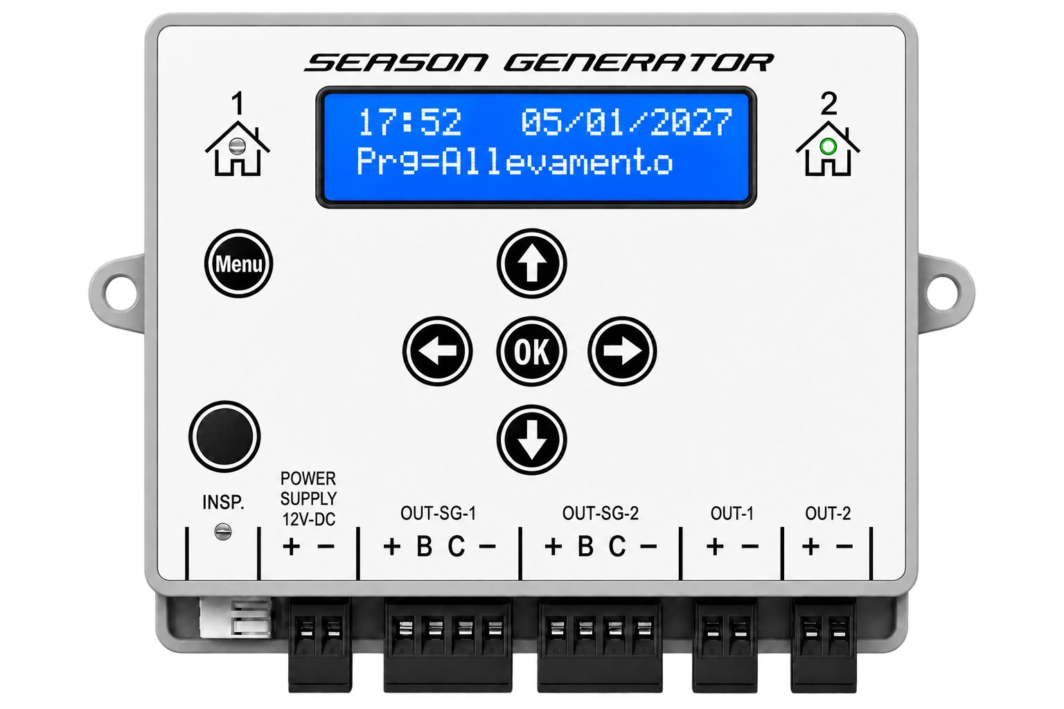
Control panel
The main buttons are MENU, OK, directional arrows and INSP..
Security
General warnings
Read the manual carefully before installing and using the device. Keep the instructions for future reference.
The installation must be carried out by qualified personnel, in compliance with the electrical standards applicable in the country of installation.
Before any work on the device or connections:
- disconnect the power;
- check the absence of voltage;
- wait for the device to completely turn off.
Power
SOL-LED works exclusively with stabilized 12-24 V DC power supply.
Never connect the device directly to the 230 V AC electrical mains.
Use suitable, stabilized and sized power supplies based on the connected LED load.
Installation environment
The device is intended for internal use.
Do not install:
- outside;
- in humid or wet environments;
- in the presence of condensation;
- near heat sources;
- in containers without ventilation.
Historical protection rating: IP20.
Water, splashes and baths
SOL-LED, power supply, LED bars, connectors and cables are not protected against water jets, splashes or immersion, unless a different IP rating is expressly indicated on the plate of the individual product.
On farms, position drinking troughs and bath tubs so that water and splashes cannot reach the control unit, power supply, connections or LED bars. Do not install the bars under bathroom spots or in areas where water can drip onto the connectors.
If a component or cable gets wet:
- immediately remove the upstream power supply;
- do not touch connectors or electrical parts while they are wet;
- do not reactivate the system until it has been dried, checked and deemed suitable by qualified personnel.
Water and condensation can cause short circuits, corrosion, overheating and damage to equipment.
Loads allowed
The outputs are designed for LED systems compatible with 12-24 V DC DC power supply.
Do not connect:
230 Vlamps;- external LED drivers;
- LED power supplies;
- inductive loads;
- devices not compatible with low voltage PWM control.
Maximum current per output: 2,5 A.
Prohibitions
Do not open, modify or tamper with the device.
Do not exceed the nominal limits indicated.
Do not replace internal components. The internal fuse is not intended for user replacement.
In the event of a fault, abnormal smell, failure to start or irregular behavior, disconnect the power and contact the dealer or authorized assistance.
Panel, Indicators and Terminals
This page shows how to recognize the SOL-LED panel and how to distinguish the available terminals. The images serve as a practical reference during installation: first identify the type of LED bar used, then choose the correct output.
General view
The following diagram identifies the display, buttons, lights of the two rooms, night inspection button, optional terminal for the remote button and all the power and output terminals.
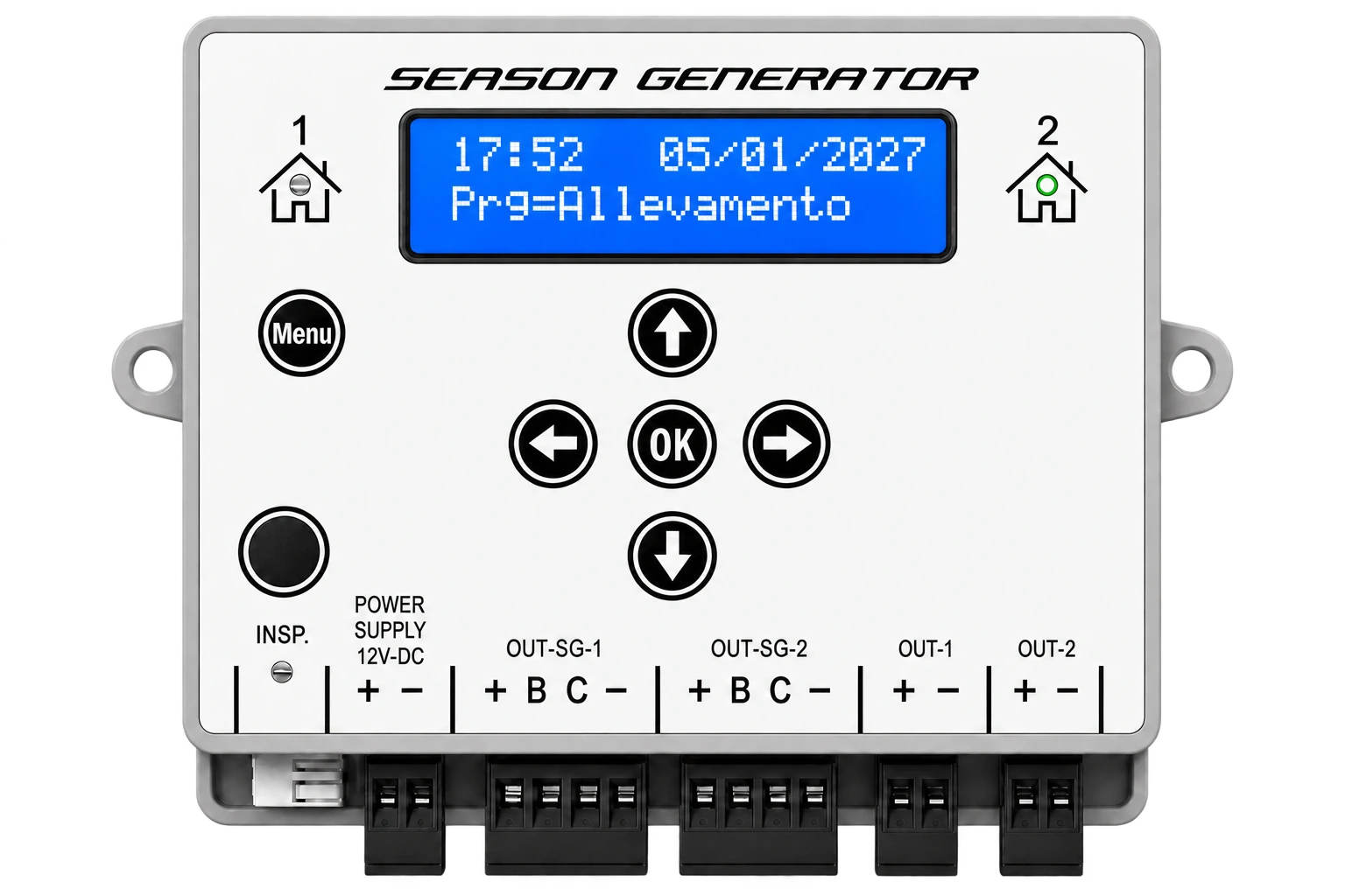
The SOL-LED can manage two separate programs, indicated as room 1 and room 2. The LEDs next to the room symbols indicate which room is being viewed at that moment.
Buttons and lights
| Element | Function |
|---|---|
MENU | Enter the menu and move to the next item. When changing time/date, increase the year. |
OK | Confirm the displayed value and save the setting. |
| up arrow | Increase the value or move to the next option. |
| down arrow | Decreases the value or moves to the previous option. |
| left arrow | When changing times, increase the hour. |
| right arrow | Change rooms in the operating screens. When changing date/time, increase the month. |
INSP. | Activates and manages the night inspection. |
| LED room 1 / room 2 | Indicates which room is selected and displayed. |
| LED inspection | Reports that night inspection is active. |
In the manual, MENU, OK and INSP. are the names written on the panel. The four directional keys are referred to as up arrow, down arrow, left arrow and right arrow, because they are represented by the arrow symbol on the panel.
Power supply 12-24 V DC
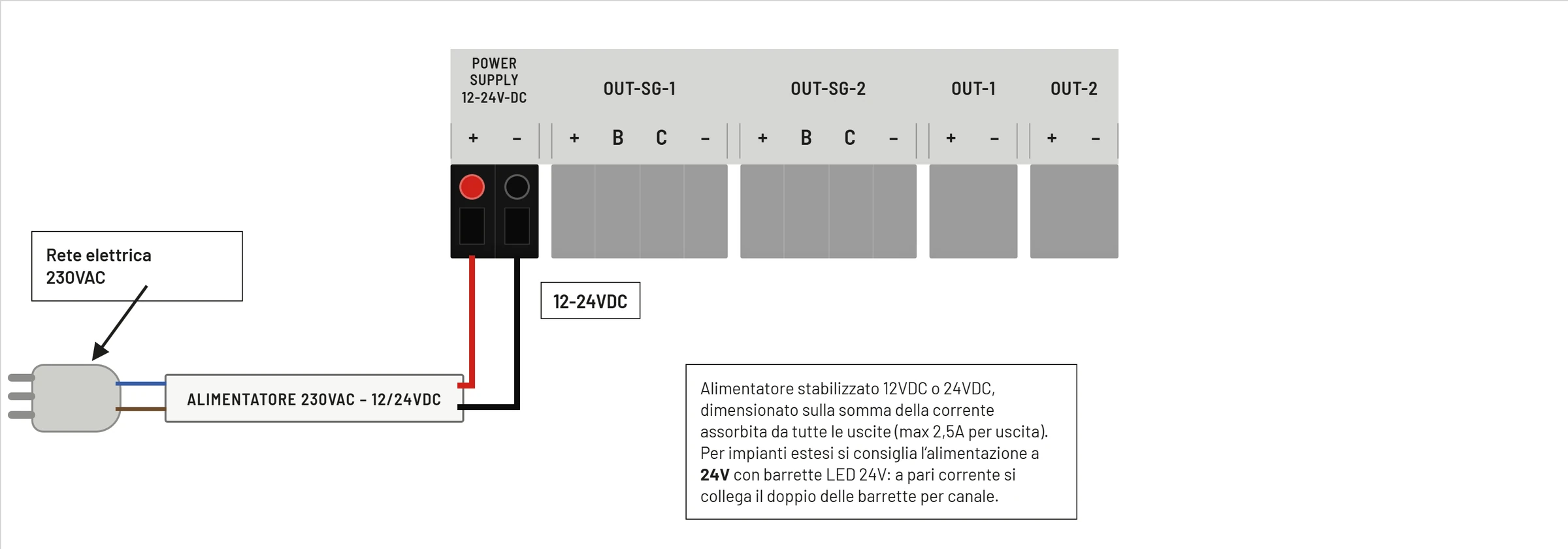
SOL-LED does not connect directly to the mains. The 230 V AC network must power an external stabilized power supply; the output of the power supply then enters the POWER SUPPLY 12-24V DC terminal of the device.
| Clamp | Function |
|---|---|
+ | Power supply positive 12-24 V DC |
- | Power negative |
The power supply must be sized on the sum of the current absorbed by all the outputs used. Each output of the SOL-LED can deliver a maximum of 2,5 A.
For large systems it is advisable to use the 24 V power supply and LED bars: for the same current, a greater quantity of bars can be connected compared to a 12 V system.
Season Generator PRO 4-wire outputs
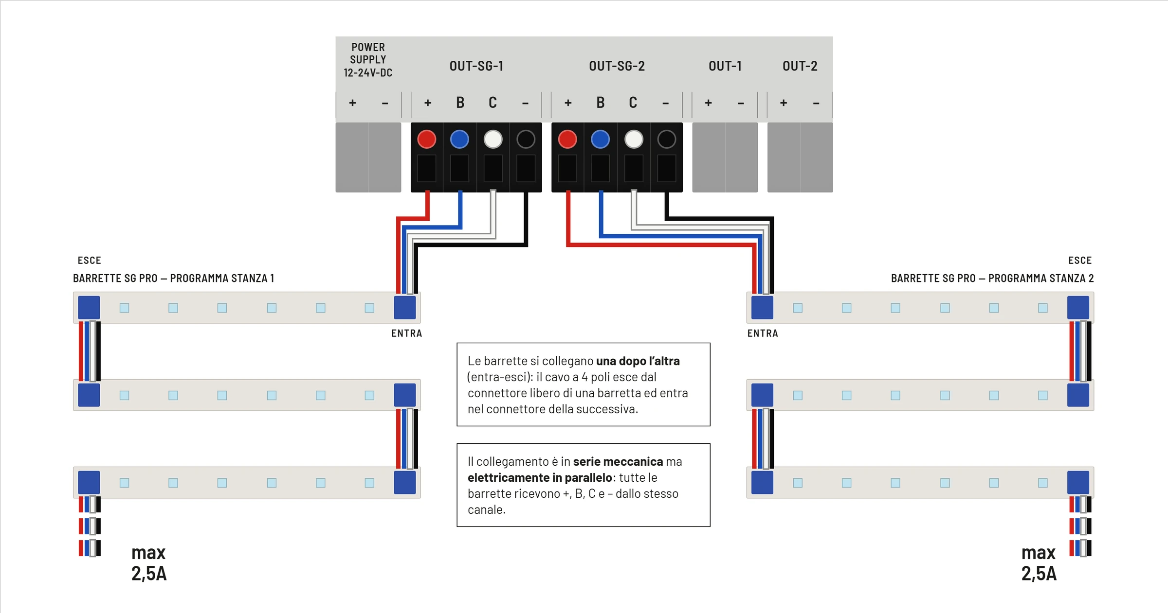
The OUT-SG-1 and OUT-SG-2 outputs are dedicated to the Season Generator PRO 4-wire bars. OUT-SG-1 follows the program of stanza 1; OUT-SG-2 follows the program of room 2.
| Clamp | Conductor Color | Function | Limit |
|---|---|---|---|
+ | red | positive LED bar power supply | 2,5 A max |
B | blue | blue LED channel / night light | 100 mA max |
C | white | main PWM reference | 32 mA max |
- | black | common negative / GND | 2,5 A max |
The bars are connected one after the other using the in-out system: the cable enters the first bar and goes out again towards the next. From a mechanical point of view the bars are in a chain, but electrically they remain in parallel on the same channel.
2-wire commercial LED outputs
The OUT-1 and OUT-2 outputs are dedicated to 12-24 V DC 2-wire commercial LED bars or strips. OUT-1 follows the program of room 1; OUT-2 follows the program of room 2.
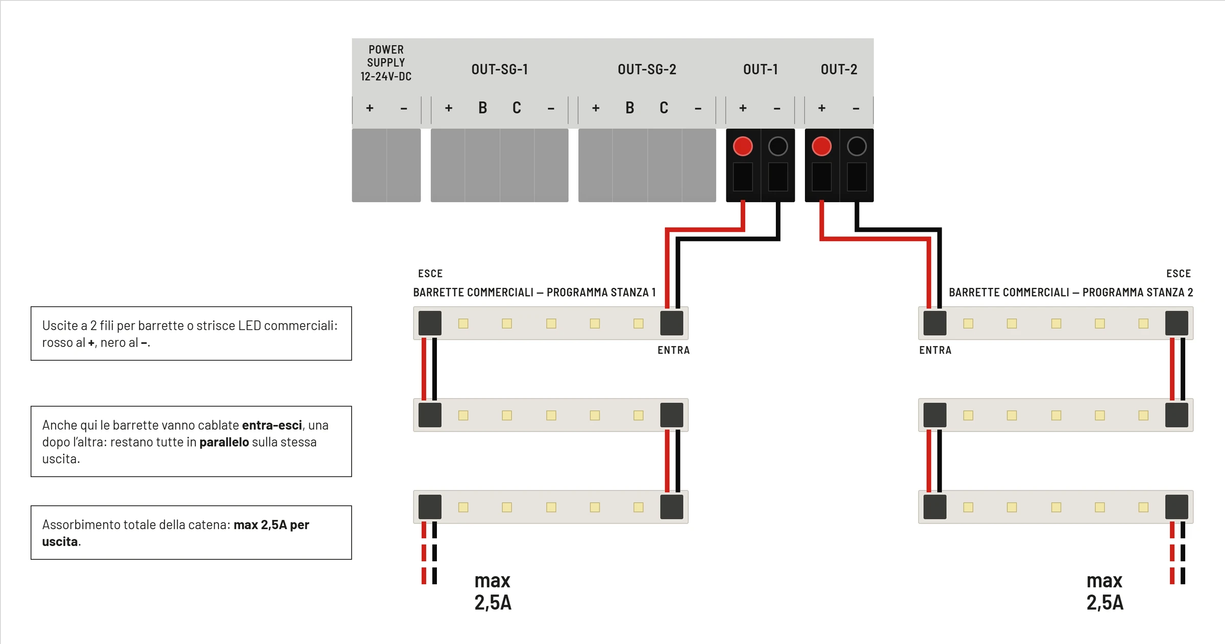
| Clamp | Typical Conductor Color | Function | Limit |
|---|---|---|---|
+ | red | positive LED bar power supply | 2,5 A max |
- | black | common negative | 2,5 A max |
Even with commercial bars, the in-out connection must keep the bars in parallel on the same output. The total absorption of the chain connected to a single output must not exceed 2,5 A.
Difference between 2-strand bars and 4-strand SG PRO
The following diagram shows the conceptual difference between a 2-wire commercial bar and a 4-wire Season Generator PRO bar.
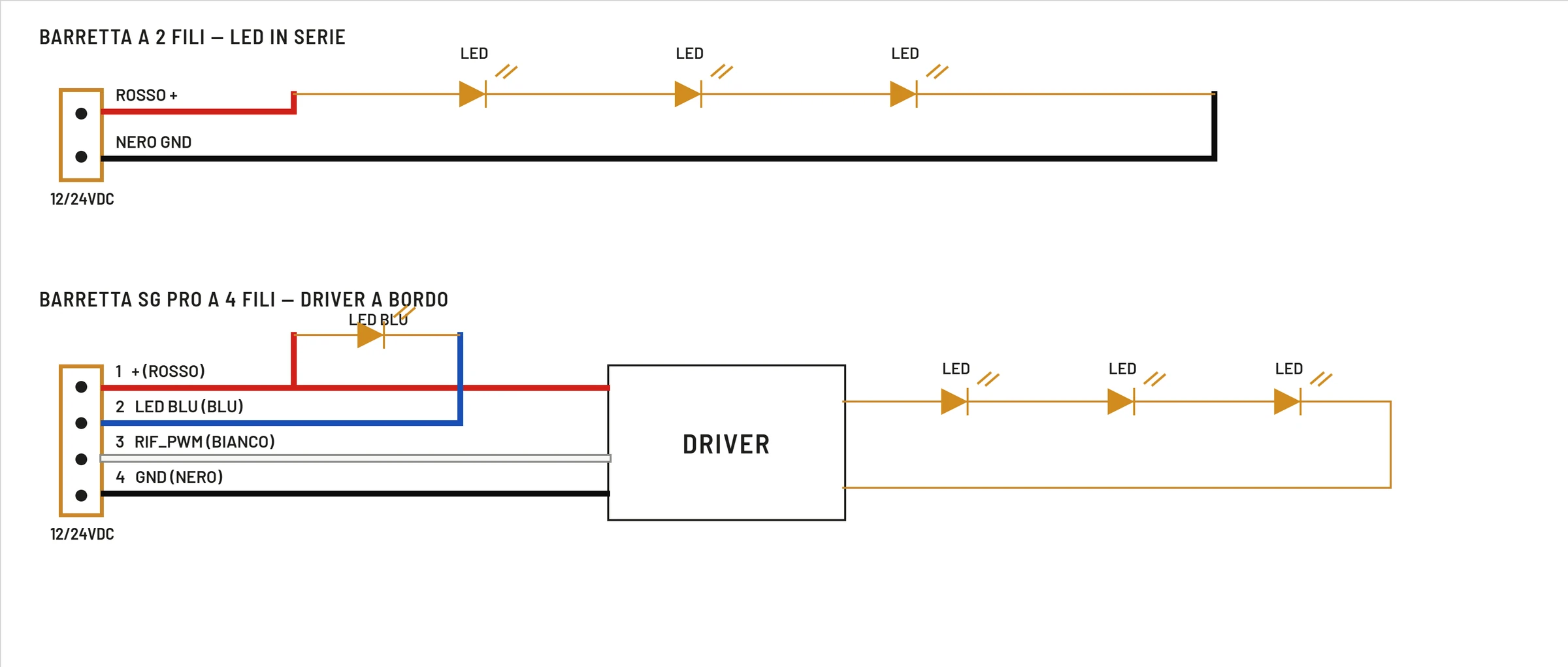
In 2-wire bars the SOL-LED directly powers the LED branch via positive and negative. In the 4-wire SG PRO bars there is an on-board driver: in addition to the power supply, the bar receives dedicated signals for regulation and for the blue LED.
For this reason it is not necessary to exchange the types of outputs: an SG PRO bar must be connected to the OUT-SG outputs, while a commercial 2-wire bar must be connected to the OUT outputs.
Optional accessories
The optional terminal of the night inspection button allows you to remote the INSP. command when required by the kit or the diagram supplied.
Sensors, remote buttons or other accessories must be connected only according to the wiring diagram supplied with the specific kit. Never apply unexpected voltages to the accessory terminals.
Installation
Check before connecting
Before powering SOL-LED check:
- stabilized power supply
12-24 V DC; - correct polarity on
+and-; - maximum current of each output not exceeding
2,5 A; - compatible LED loads;
- correct tightening of the clamps;
- absence of exposed wires or short circuits.
Connect the power
Before connecting the wires, see the diagram in Panel, Indicators and Terminals. The 230 V mains must only reach the external power supply; SOL-LED receives only stabilized 12-24 V DC.
- Turn off the power supply.
- Connect the positive of the power supply to the
+terminal. - Connect the negative of the power supply to the
-terminal. - Check the polarity again.
- Power the device.
Do not connect the device directly to the 230 V AC network.
Connect the LED bars
Choose the type of output based on the bar used.
For SeasonGenerator PRO bars use OUT-SG-1 and OUT-SG-2.
For 2-wire commercial LED bars use OUT-1 and OUT-2.
Do not use incompatible links on the same bar at the same time.
First ignition
When first turned on or after loss of saved parameters, the device loads default values and sets the clock.
Main default values:
| Parameter | Default |
|---|---|
Sunrise duration | 10 minutes |
Sunset duration | 10 minutes |
Inspection time | 1 minute |
Inspection time | 1 minute |
Night Light | OFF |
Max. Brightness | 80 % |
Energy saving | Disabled |
Language | Italian, if the saved value is invalid |
Recommended configuration
- Set time and date.
- Select your language.
- Select the room to configure with the right arrow.
- Choose the program.
- Set
Sunrise durationandSunset duration. - Set
Max Brightness. - Configure any night light, inspection and energy saving.
- Repeat for the other room, if used.
Commands and Rooms
Main page
In normal operation the display automatically scrolls through some information.
The main screens are:
| Screenshot | Information |
|---|---|
Prg= | active program of the selected room |
Sunrise / Sunset | times calculated for the current day |
Total light hr | duration of current daylight |
Consumption / Current | current measured on the selected room |
Days counter | displayed for the Personal |
Each screen remains visible for approximately 5 seconds.
Pressing a key temporarily stops automatic scrolling. After about 30 seconds without keys the device returns to the main page.
Room change
Press right arrow to change rooms.
The front light indicates the room displayed.
Changes made from the menu are applied to the selected room.
Enter the menu
Press MENU from the home page.
The first menu displayed is:
Use the program
Pressing MENU again takes you to the other configuration pages.
General key rules
| Action | | button
| --- | --- |
| Go to the next menu item | MENU |
| Enter the entry or confirm | OK |
| Increase value/option | up arrow |
| Decrease value/option | down arrow |
| Increment time in the time | fields left arrow |
| Increment minute in time fields | up arrow |
| Changing rooms in the operating screens | right arrow |
Saving
When you confirm a parameter with OK, the device saves the setting in non-volatile memory.
The settings remain stored even after switching off.
Automatic return
If you remain in a menu without pressing any keys, after about 30 seconds the device returns to the main page.
Programs
Menu path
Route:
MENU -> Use the program
Screenshots:
Use the programPrg:
Use the up and down arrows to scroll through the programs. With OK you confirm the displayed program.
Programs available
SOL-LED exposes the following programs:
The names of the preloaded tables should not be interpreted as an exclusive restriction to the indicated species. They are practical names assigned to different light profiles: each table has its own seasonal trend, with minimum and maximum length of the day, growth and reduction of hours, sunrise and sunset times and ramp progression. For this reason, a table called, for example, Song thrush, REDWING, Fieldfare, Canaries or Crest Agi can also be used in different situations, when the light profile better corresponds to the objective of the breeder or user.
| Value | Display Name | Usage |
|---|---|---|
0 | Personal | personalized program with daily variation + / - minutes |
1 | Standard | general light profile, useful when there are multiple needs or multiple species in the same room |
2 | Song thrush | preloaded light profile identified with this name |
3 | REDWING | preloaded light profile identified with this name |
4 | Skylark | preloaded light profile identified with this name |
5 | Fieldfare | preloaded light profile identified with this name |
6 | Breeding | preloaded light profile oriented towards breeding |
9 | Finches | preloaded light profile identified with this name |
10 | Canaries | preloaded light profile identified with this name |
11 | Crest Agi | preloaded light profile identified with this name |
12 | Custom2 | personalized program from start date to end date |
13 | AstroGPS Timer | astronomical program from coordinates |
14 | Manual | program with fixed times set by the user |
Table programs
Table programs use times already stored in the device.
On the Season Generator website it is possible to see the behavior of the main tables and the times they represent day by day:
To advance or postpone the times in the table compared to those displayed, simply move the programmer date forwards or backwards. In this way the table also moves automatically and the user can adapt the period of greatest light to their needs.
For each day the device obtains:
- dawn time;
- sunset time;
- total duration of light.
The user can separately edit:
Sunrise duration;Sunset duration;Max brightness;- night light;
- night inspection;
- energy saving.
Personal Program
The Personal program does not use a fixed annual table.
The user sets:
- initial time of dawn;
- initial time of sunset;
- daily increase or decrease of sunrise;
- daily increase or decrease of sunset;
- number of days of application.
Detailed operation is described in the Personal Table chapter.
Manual Program
The Manual program uses fixed times set by the user. It does not apply daily increments and does not use an annual table.
When you confirm Prg: Manual, the display shows the sequence:
Sunrise beginSunset beginSunrise durationSunset duration
Use Manual when you want to keep the same on and off times every day.
Personal Program2
The Custom2 program automatically calculates a progression between an initial photoperiod and a final photoperiod.
The user sets departure date and times, arrival date and times, sunrise duration and sunset duration. The device then calculates the intermediate times day by day.
The detailed operation is described in the chapter Personal Table 2.
Program AstroGPS Timer
The AstroGPS Timer program calculates times using geographic coordinates.It is used when you want to simulate the natural trend of the sun in a place, maintaining control of the photoperiod inside a closed room.
Detailed operation is described in chapter AstroGPS.
Personal Table
What is it for
The Personal program allows you to create a personalized photoperiod.
The user sets the initial times and indicates how many minutes to change sunrise and sunset each day.
Activation
Route:
MENU -> Use the program -> Prg: Personal -> OK
After confirmation, the display guides the configuration in sequence.
Reset day counter
Screenshot:
Reset dayCount :
Select:
| Option | Effect |
|---|---|
YES | resets the day counter and starts the new progression |
NO | keeps the current counter |
Use up arrow or down arrow to change option and OK to confirm.
Start of sunrise time
Screenshot:
Sunrise begin
Keys:
| Field | | button
| --- | --- |
| Now | left arrow |
| Minutes | up arrow |
| Confirm | OK |
Sunset start time
Screenshot:
Sunset begin
Keys:
| Field | | button
| --- | --- |
| Now | left arrow |
| Minutes | up arrow |
| Confirm | OK |
Sunrise increase or decrease
Screenshot:
+/-min Sunrise
The value is expressed in minutes per day.
| button Effect | |
|---|---|
| up arrow | increase the value to +100 |
| down arrow | decreases the value to -100 |
OK | confirm |
Positive values progressively bring dawn earlier. Negative values progressively postpone sunrise.
Example: initial dawn 07:00, value +1, duration 10 days. After 10 days the sunrise will be around 06:50.
Increase or decrease sunset
Screenshot:
+/-min Sunset
The value is expressed in minutes per day.
| button Effect | |
|---|---|
| up arrow | increase the value to +100 |
| down arrow | decreases the value to -100 |
OK | confirm |
Positive values progressively postpone sunset. Negative values progressively bring the sunset earlier.
Example: initial sunset 18:00, value +3, duration 10 days. After 10 days sunset will be around 18:30.
Duration days
Screenshot:
How many days?
Set how many days to apply the increases or decreases.
Values:
- minimum
0days; - maximum
365days.
With OK you save and return to the main page.
Complete example
Settings:
| Parameter | Value |
|---|---|
| Initial dawn | 07:00 |
| Initial sunset | 18:00 |
+/-min Sunrise | +1 minute |
+/-min Sunset | +3 minutes |
How many days? | 10 |
Result after 10 days:
- dawn anticipated by approximately 10 minutes;
- sunset postponed by approximately 30 minutes;
- total increase of approximately 40 minutes of daily light.
Operational note
The device updates the progression once a day. If creating a new schedule, choose YES over Reset day to start over from day 0.
Personal Table 2
What is it for
The Custom2 program allows you to create a seasonal progression starting from a starting date and arriving at a final date.
It helps when you know the photoperiod you want to have at the beginning and what you want to achieve at the end. The device automatically calculates all intermediate steps day by day.
Activation
Route:
MENU -> Use the program -> Prg: Personal2 -> OK
After confirmation, the display guides the configuration in sequence.
Photoperiod start date
Screenshot:
Start date pho
The initial date is taken from the current date of the device. Before programming Custom2, therefore, check that the time and date are correct.
Starting times
Screenshots:
Sunrise todaySunset today
These values indicate sunrise and sunset of the initial day.
To change the times:
| Field | | button
| --- | --- |
| Now | left arrow |
| Minutes | up arrow |
| Confirm | OK |
End date
Screenshot:
End date photo
Set the date by which the program must reach the final photoperiod.
Keys:
| Field | | button
| --- | --- |
| Day | down arrow |
| Month | right arrow |
| Year | MENU |
| Confirm | OK |
The end date must be later than the start date.
End times
Screenshots:
Sunrise endSunset end
These values indicate sunrise and sunset to be achieved on the final date.
Sunrise and sunset duration
At the end of the configuration the display asks:
Sunrise durationSunset duration
These values indicate how many minutes it takes for the light to rise in the morning and fall in the evening.
Automatic operation
Once the program is saved, the device calculates the intermediate times between the starting point and the ending point every day.
If, for example, you set a season that starts with sunrise at 08:00 and sunset at 18:00, and ends with sunrise at 06:30 and sunset at 20:00, the device gradually changes the times day after day until the set result is achieved.
The variation does not happen all at once: the photoperiod changes progressively.
AstroGPS
What is it for
The AstroGPS Timer program automatically calculates sunrise and sunset using geographic coordinates.
It is used when you want to reproduce the natural pattern of the sun in a place, while maintaining control of the lighting inside a closed room.
The device uses two references:
Controller place, i.e. the real position in which the device is installed;Simulated place, i.e. the place whose light pattern you want to reproduce.
Menu path
Route:
MENU -> Usa il programma -> Prg: AstroGPS Timer -> OK
Screenshots:
Controller place/Lat:Controller place/Long:Controller place/UTC:Simulated place/Lat:Simulated place/Long:Twilight:
Control unit location
The Controller place indicates where the device is physically located.
The real position is used to correctly place the local solar noon and keep the simulation consistent with the local time.
Latitude and longitude
Latitude is displayed as:
N+DDD.DD or S-DDD.DD
Longitude is displayed as:
E+DDD.DD or O-DDD.DD
On the display the letter O indicates West.
Keys:
| Action | | button
| --- | --- |
| Move the cursor | left arrow / right arrow |
| Increase the | value up arrow |
| Decrease the | value down arrow |
| Confirm | OK |
UTC
The UTC: screen sets the difference between local time and UTC.
For Italy, under normal conditions, the reference is:
+01:00during standard time;+02:00during summer time, if you want to follow summer civil time.
Simulated location
The Simulated place is the place where we want to reproduce the natural cycle of light.
The device uses these coordinates to calculate the length of the day and, if enabled, the twilight stretch.
Twilight
The Twilight: screen allows you to enable or disable twilight.
Values:
Enabled;Disabled.
With dusk enabled, light starts rising before the calculated sunrise and ends after sunset, simulating a more natural transition.
With dusk disabled, the device uses sunrise and sunset as primary references.
Recommended checks
After configuring AstroGPS Timer, check:
- device time and date;
- coordinates of the real place;
- offset
UTC:; - coordinates of the simulated place;
- status of
Twilight:; - sunrise and sunset times displayed on the main page.
Ramps, Intensity and Brightness
The ramps regulate how the light increases in the morning and decreases in the evening. They serve to avoid sudden switching on and off, making the transition between darkness, day and night more gradual.
The Intensity function allows you to establish how much light the system should reach during the day. It does not change the program times: it limits the maximum level reached by the ramp.
Sunrise duration
Route:
MENU -> Sunrise Duration
Sunrise duration adjusts the time it takes for light to go from dim to daylight brightness.
Values:
- minimum
1minute; - maximum
100minutes; - default
10minutes.
Use up arrow and down arrow to edit. Press OK to confirm.
Sunset duration
After confirmation of Sunrise duration, the display shows:
Sunset duration
Sunset duration adjusts the time it takes for the light to gradually dim before turning off or turning on the night light.
Values:
- minimum
1minute; - maximum
100minutes; - default
10minutes.
Press OK to confirm and save.
Light intensity
Route:
MENU -> Intensity
The function can work in two ways:
Fixed, with a maximum value that is always the same;Seasonal, with a minimum and maximum value that the device automatically interpolates during the season.
Fixed mode
In Fixed mode, the device uses only one maximum limit.
Values:
- minimum
10 %; - maximum
100 %; - default
80 %.
Examples:
| Value | Effect |
|---|---|
100 % | maximum brightness available |
80 % | default value |
50 % | full light limited to about half power |
10 % | minimum limit that can be set |
Seasonal Mode
The Seasonal mode allows you to automatically vary, during the season, not only the duration of the photoperiod but also the maximum intensity of the lighting.
The user sets:
Mini season;Max season.
The device automatically calculates intermediate values day by day.
Example:
- minimum period:
40 %; - maximum period:
100 %.
During the growing phase of the season, the maximum value gradually increases. During the decreasing phase, the process occurs in reverse.
If for a certain day the calculated value is 65 %, during dawn the light progressively rises up to 65 %, not up to 100 %. During the period of full light it remains at that level and, at sunset, it gradually drops from that value.
Effect on outputs
The intensity limit acts on the main light ramp of the selected room.
The night light has a separate parameter, described in the chapter Night Light.
Current protection
The device controls the current on the outputs. If the current exceeds the internal protection limit, the ramp of the affected room is limited.
If the display shows abnormal absorption or the light does not rise as expected, check the load, wiring and power supply.
Night Light
What is it for
The Night Light function maintains reduced light during the night phase.
It is useful when you want to avoid complete darkness or simulate weak night lighting.
Menu path
Route:
MENU -> Night Light
Screenshot:
Night Light
Setting
Use up arrow and down arrow to adjust the value.
Values:
OFFwhen the value is0 %;- maximum
50 %; - default
OFF.
Press OK to save.
Operation
When the daylight is turned off, the nightlight gradually rises to the set value.
When a new daylight phase starts, the night light gradually turns off.
If energy saving is active in the set time slot, the night light can be temporarily disabled by the device.
Practical advice
Use low values for night light. Too high a level can reduce the perceived difference between day and night.
Night inspection
What is it for
The INSP. function allows you to enter the room when the light is off and make a short visit while disturbing the birds as little as possible.
By pressing the button, the device starts a quick little dawn: the light gradually rises instead of turning on suddenly.
When the light is bright enough to see into the room, press INSP. again. In this way the level is blocked at the point reached, without causing the light to rise further.
At the end of the visit, press INSP. again to exit. The light must go off: only then will the device return to the main program. If the inspection remains active, the light can remain on and the normal day-night cycle is excluded.
Using the INSP button.
The INSP. button works in cycles:
| Pressure | Status |
|---|---|
| first press | inspection active, light up and warning light on |
| second press | light stuck at the level reached, light flashing |
| final pressure | exited inspection, light off |
When the inspection LED is off, the device returns to following the automatic programs.
Before leaving the room, check that the inspection LED is off. If it stays on or flashes, the inspection may keep the light out of normal programming.
Inspection entry duration
Route:
MENU -> Inspection Input
This parameter regulates the duration of the inspection start-up ramp.
Values:
- minimum
1minute; - maximum
100minutes; - default
1minute.
Inspection exit duration
After Inspection time the display shows:
Inspection time
This parameter adjusts the duration of the inspection shutdown ramp.
Values:
- minimum
1minute; - maximum
100minutes; - default
1minute.
Selection of inspection rooms
After the entry and exit durations, the display shows:
Night insp.sel
Options:
| Display option | Effect |
|---|---|
room 1 | inspection applied to room 1 |
room 2 | inspection applied to room 2 |
room 1+2 | inspection applied to both |
Use up arrow and down arrow to choose and OK to confirm.
Remote accessory
The inspection button can be remoted with an optional Season Generator kit, or with a clean button contact when required by the electrical diagram supplied.
The remote button can be installed, for example, near the door of the room or inside an electrical system. Pressing it gives the same effect as the INSP. button on the programmer.
The remote contact must not carry external voltage to the device.
Energy Saving
What is it for
Energy saving allows you to reduce the consumption of the system by exploiting, when available, the natural light coming from outside.
If during some hours of the day the light entering through the windows already illuminates the room correctly, it is not necessary to keep the LED bars or system lamps switched on. The control unit can then temporarily turn off the artificial lighting and then automatically return to the daily program.
On the SOL-LED the function works on a timed basis: the user sets a period of the day in which he knows that the room normally receives sufficient natural light.
These modes are managed:
| Display Mode | Usage |
|---|---|
Disabled | no energy savings |
No sensor | switching off in the set time slot |
Menu path
Route:
MENU -> Energy Saving -> OK
Screenshot:
Energy saving
Use up arrow and down arrow to change mode and OK to confirm.
Disabled mode
Select Disabled when you want to always follow the light program without saving interventions.
Press OK to save and return to the main page.
Sensorless mode
The No sensor mode turns off the light in a time slot set by the user.
This mode does not require sensors. It is indicated when the natural lighting of the room is quite predictable: for example, if the program foresees sunrise at 06:30 and sunset at 21:00, but between 11:00 and 14:00 the room receives sufficient light from the windows, that period can be set as a saving period.
Menu sequence:
Turn off lights/From hoursTurn off lights/Up to hoursTurn-oFF Turn-ON/Gradual:
Shutdown time
To the From hours screen:
| Field | | button
| --- | --- |
| Now | left arrow |
| Minutes | up arrow |
| Confirm | OK |
Restart time
At the Up to hours screen use the same keys.
Gradual Off-On
| Option | Effect |
|---|---|
YES | entry and exit from the band with gradual progress |
NO | immediate switching off and on again |
Press OK to save.
Practical note
Set the savings band only when you are sure that natural light is sufficient for the room during those hours. Once the interval is over, the device automatically resumes normal program management.
Time, Date and Language
Change time and date
Route:
MENU -> Change Time and Date -> OK
Screenshots:
ModifyTime and DateTime Date
When you enter the change, the device temporarily suspends the automatic update of the clock.
Keys for changing time/date
| Field | | button
| --- | --- |
| Now | left arrow |
| Minutes | up arrow |
| Day | down arrow |
| Month | right arrow |
| Year | MENU |
| Confirm and update RTC | OK |
The year increases to 2099; after the limit it starts again from 2018.
Press OK to save the clock and return to the main page.
Room clock
SOL-LED uses the same time reference for both stanzas.
The two rooms may have different programs and parameters, but the date and time are common.
Choice of language
Route:
MENU -> Choose language
Use up arrow and down arrow to select language and OK to confirm.
Available languages:
| Value | Language |
|---|---|
0 | Italian |
1 | English |
2 | French |
3 | German |
4 | Spanish |
5 | Portuguese |
6 | Dutch |
7 | Ivrit latin |
8 | Polish |
9 | Romanian |
10 | Turkish |
11 | Latin Greek |
If the saved value is invalid, the device reverts to Italian.
Use Rooms
What is it for
The Room use function allows you to choose whether to use SOL-LED for two independent rooms or for a single room lit by two synchronized outputs.
In the manual, the term room indicates one of the two outputs controlled by the device.
Menu path
Route:
MENU -> Use rooms
In the menu cycle, the item is found after the main configuration functions and before returning to the main page.
Available values
| Display value | Operation |
|---|---|
1 room | stanza 2 copies stanza 1 |
2 rooms | the two rooms work independently |
2 room mode
In 2 rooms mode, each output can have separate settings:
- program;
- dawn duration;
- sunset duration;
- intensity;
- night light;
- night inspection;
- energy saving;
- coordinates
AstroGPS Timer; PersonalandCustom2parameters.
The right arrow key selects which room is viewed and edited.
1 room mode
In 1 room mode, the operating room is room 1.
Stanza 2 follows stanza 1 for:
- main light;
- night light;
- inspection ramp;
- load-related protections.
Use 1 room when two LED groups illuminate the same room and you want to obtain the same dawn and dusk cycle on both outputs.
Use 2 rooms when the two environments must have different times or programs.
Confirm
Use the up or down arrow to change the value.
With OK the device saves the parameter and returns to the main page.
Troubleshooting
The device does not turn on
Check:
- power supply turned on;
- voltage
12-24 V DC; - correct polarity;
- clamps tightened;
- absence of short circuits.
If the device remains off, disconnect the power and contact service or dealer. Do not open the device.
The light does not turn on
Check:
- selected room;
- active program;
- time and date;
- value
Max brightness; - correct connection of the LED bar;
- current absorbed by the load;
- possible active energy saving.
The light stays on during the night
Check:
INSP.button and inspection LED;- value
Night Light; - sunrise/sunset times;
- selected program.
If the inspection LED is on or flashing, press INSP. until it turns off.
The light turns off during the day
Possible causes:
- energy saving
No sensoractive in the set time slot; - overcurrent or load beyond limit;
- incorrect wiring.
The two rooms do not follow the same program
SOL-LED manages two separate parameter sets.
Press right arrow to select the correct room and check:
- program;
- dawn duration;
- sunset duration;
- maximum brightness;
- night light;
- energy saving.
The Personal program does not restart from day one
When creating a new Personal program, select YES over Reset day.
If you select NO, the device keeps the previous day counter.
Energy saving does not turn off the light
Check:
No sensormode;- time
From hours; Up to hourstime;Gradual Off-Onsetting;- device time and date.
The menu automatically returns to the main page
It's normal. After about 30 seconds without keys the device returns to the main page.
Technical Specifications
General data
| Voice | Value |
|---|---|
| Model | SOL-LED |
| Brand | Season Generator |
| Product Type | professional photoperiod controller |
| Startup display | Season Generator / SoL-Led |
| Interface | LCD display, MENU, OK keys, arrows, INSP. |
| Languages | 12 |
Power
| Voice | Value |
|---|---|
| Rated voltage | 12-24 V DC stabilized |
| Direct connection to network | not expected |
| Installation type | internal |
| Historical degree of protection | IP20 |
| Historical operating temperature | 0 C - +40 C |
LED outputs
| Exit | Usage | Maximum current |
|---|---|---|
OUT-SG-1 / OUT-SG-2 | slashes SeasonGenerator PRO | 2,5 A for exit |
OUT-1 / OUT-2 | 2 wire commercial LED bars 12-24 V DC | 2,5 A for exit |
Main light adjustment: PWM, limited by the Intensity parameter.
Parameter limits
| Parameter | Values | Default |
|---|---|---|
Sunrise duration | 1 - 100 min | 10 min |
Sunset duration | 1 - 100 min | 10 min |
+/-min Sunrise | -100 - +100 min/day | 0 |
+/-min Sunset | -100 - +100 min/day | 0 |
How many days? | 0 - 365 days | 0 |
Max. Brightness | 10 % - 100 % | 80 % |
Night Light | OFF - 50 % | OFF |
Inspection time | 1 - 100 min | 1 min |
Inspection time | 1 - 100 min | 1 min |
Intensity | Fixed / Seasonal | Fixed |
Mid season | 10 % - 100 % | 10 % |
Max season | 10 % - 100 % | 80 % |
Language | 12 languages | Italian if invalid |
Programs
The Prg: menu manages:
Personal;Custom2;AstroGPS Timer;Manual;Standard;Song thrush;REDWING;Skylark;Fieldfare;Breeding;Finches;Canaries;Crest Agi.
Memory and clock
The settings are saved in EEPROM.
The device uses an internal clock shared by the two rooms.
Current protection
The device monitors the current of the outputs and limits the ramp if an exceeding of the internal limit is detected.
The internal protection limits must not be used as authorization to exceed the load limits indicated in the manual.
CE and WEEE compliance
Compliance
The SOL-LED device is intended for use as a professional photoperiod regulator for low DC voltage LED systems.
Conformity is assessed on the product actually supplied and the accessories used.
Reference directives:
| Scope | Reference |
|---|---|
| Electromagnetic compatibility | 2014/30/UE Directive |
| Restriction of hazardous substances | 2011/65/UE Directive and subsequent applicable amendments |
| Waste electrical and electronic equipment | 2012/19/UE Directive |
EU declaration of conformity
The manufacturer declares under his own responsibility that the product identified as:
| Voice | Value |
|---|---|
| Product | professional photoperiod controller |
| Model | SOL-LED |
| Brand | Season Generator |
complies with the applicable requirements according to the EU declaration of product conformity.
WEEE
This product falls within the regulation of waste electrical and electronic equipment.
The device must not be disposed of with household waste.
At the end of its life it must be delivered according to local rules to:
- authorized collection centers;
- collection points set up by the retailer;
- municipal separate waste collection services.
Improper disposal may result in negative impacts on the environment and penalties according to applicable legislation.
RoHS
The product must comply with applicable restrictions on the use of hazardous substances in electrical and electronic equipment.
Always check the bill of materials and the updated technical file before the final declaration.
Warranty
General conditions
The product is covered by the legal guarantee of conformity provided for by the applicable legislation.
The warranty covers defects in conformity existing at the time of delivery of the product, according to the methods and limits established by law.
Exclusions
The warranty does not cover damage resulting from:
- installation not compliant with instructions;
- improper use;
- connection to incompatible loads;
- exceeding the nominal voltage, current or power limits;
- tampering or unauthorized modifications;
- opening the device;
- overvoltages, lightning or external events;
- normal wear.
Internal fuse
The device can integrate an internal protection fuse.
The fuse is not user replaceable. In the event of failure to turn on or if the fuse is suspected to be blown, do not open the appliance and contact assistance or the retailer.
Limitation of liability
The installer and the end user are responsible for verifying the compatibility of the connected load and the conformity of the electrical system.
Failure to follow the instructions may result in the warranty being voided.
Contacts
| Voice | Given |
|---|---|
| Company name | PAGLIARIN NICOLA |
| Address | Via Colombara 23, 36024 Nanto (VI), Italy |
| Telephone | +39 389 6238692 |
info@seasongenerator.it | |
| Web | www.seasongenerator.it |