Panel, Indicators and Terminals
This page shows how to recognize the SOL-LED panel and how to distinguish the available terminals. The images serve as a practical reference during installation: first identify the type of LED bar used, then choose the correct output.
General view
The following diagram identifies the display, buttons, lights of the two rooms, night inspection button, optional terminal for the remote button and all the power and output terminals.
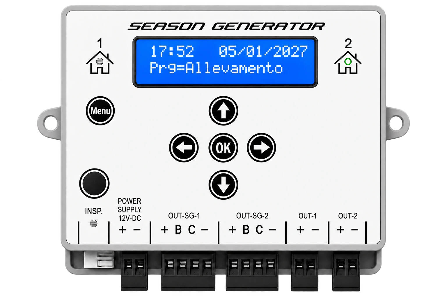
The SOL-LED can manage two separate programs, indicated as room 1 and room 2. The LEDs next to the room symbols indicate which room is being viewed at that moment.
Buttons and lights
| Element | Function |
|---|---|
MENU | Enter the menu and move to the next item. When changing time/date, increase the year. |
OK | Confirm the displayed value and save the setting. |
| up arrow | Increase the value or move to the next option. |
| down arrow | Decreases the value or moves to the previous option. |
| left arrow | When changing times, increase the hour. |
| right arrow | Change rooms in the operating screens. When changing date/time, increase the month. |
INSP. | Activates and manages the night inspection. |
| LED room 1 / room 2 | Indicates which room is selected and displayed. |
| LED inspection | Reports that night inspection is active. |
In the manual, MENU, OK and INSP. are the names written on the panel. The four directional keys are referred to as up arrow, down arrow, left arrow and right arrow, because they are represented by the arrow symbol on the panel.
Power supply 12-24 V DC
SOL-LED does not connect directly to the mains. The 230 V AC network must power an external stabilized power supply; the output of the power supply then enters the POWER SUPPLY 12-24V DC terminal of the device.
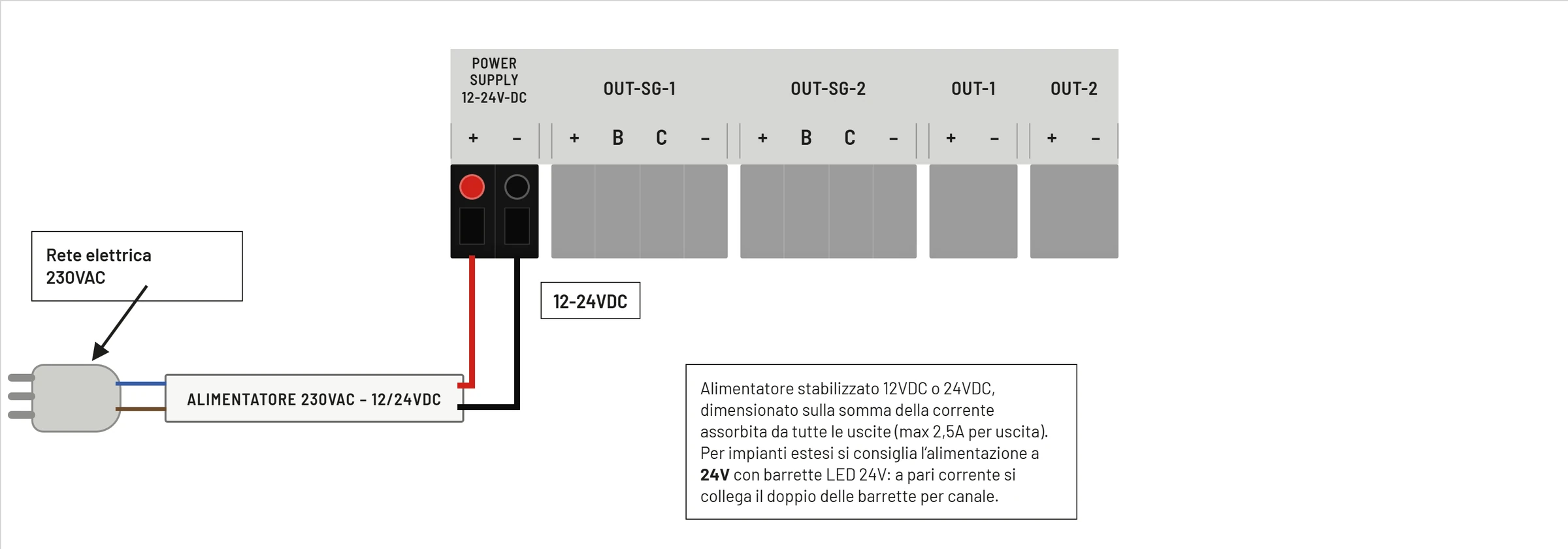
| Clamp | Function |
|---|---|
+ | Power supply positive 12-24 V DC |
- | Power negative |
The power supply must be sized on the sum of the current absorbed by all the outputs used. Each output of the SOL-LED can deliver a maximum of 2,5 A.
For large systems it is advisable to use the 24 V power supply and LED bars: for the same current, a greater quantity of bars can be connected compared to a 12 V system.
Season Generator PRO 4-wire outputs
The OUT-SG-1 and OUT-SG-2 outputs are dedicated to the Season Generator PRO 4-wire bars. OUT-SG-1 follows the program of stanza 1; OUT-SG-2 follows the program of room 2.
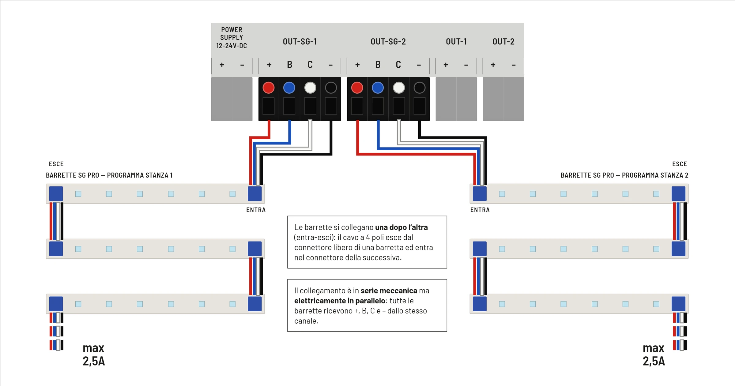
| Clamp | Conductor Color | Function | Limit |
|---|---|---|---|
+ | red | positive LED bar power supply | 2,5 A max |
B | blue | blue LED channel / night light | 100 mA max |
C | white | main PWM reference | 32 mA max |
- | black | common negative / GND | 2,5 A max |
The bars are connected one after the other using the in-out system: the cable enters the first bar and goes out again towards the next. From a mechanical point of view the bars are in a chain, but electrically they remain in parallel on the same channel.
2-wire commercial LED outputs
The OUT-1 and OUT-2 outputs are dedicated to 12-24 V DC 2-wire commercial LED bars or strips. OUT-1 follows the program of room 1; OUT-2 follows the program of room 2.
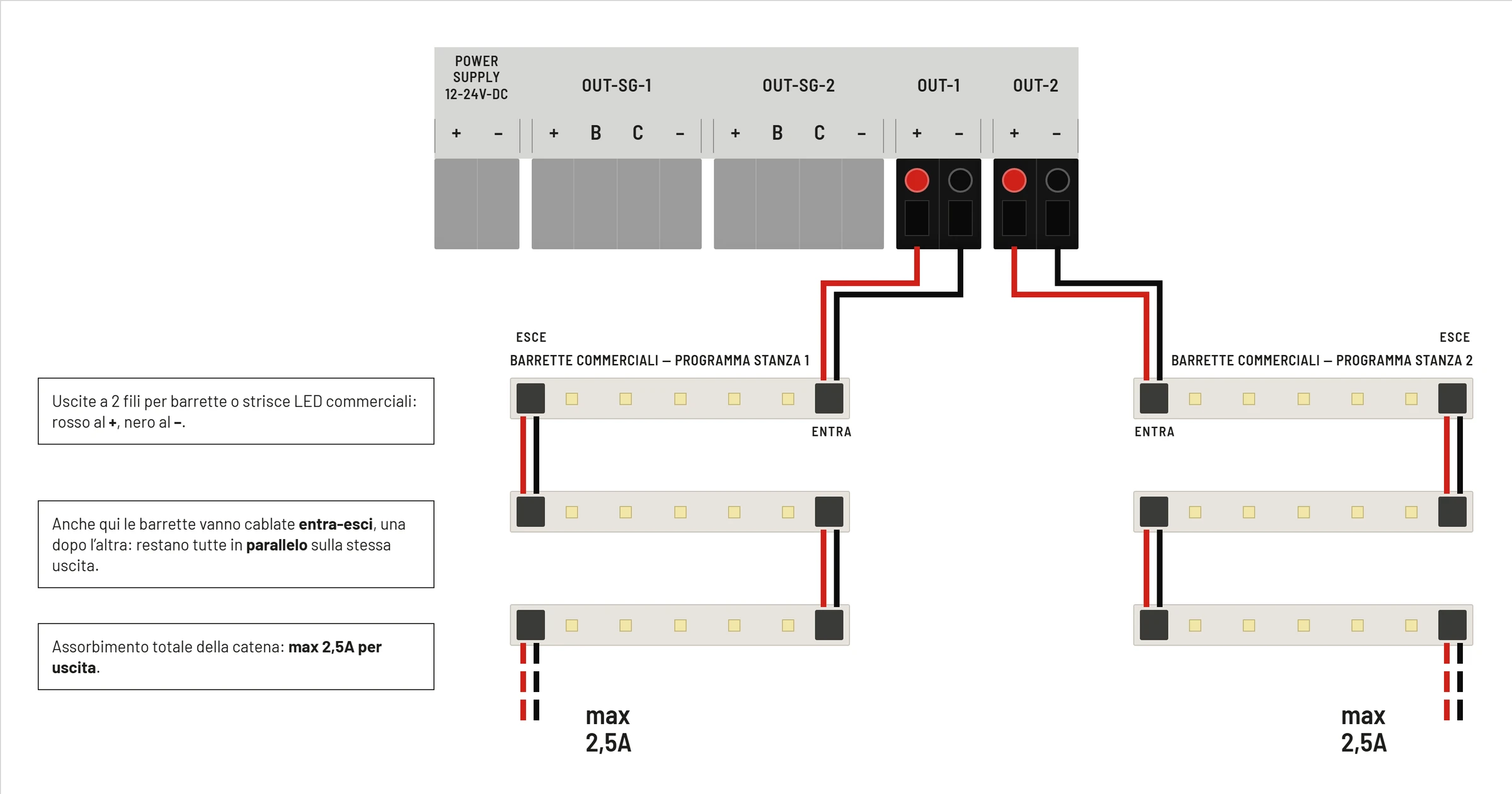
| Clamp | Typical Conductor Color | Function | Limit |
|---|---|---|---|
+ | red | positive LED bar power supply | 2,5 A max |
- | black | common negative | 2,5 A max |
Even with commercial bars, the in-out connection must keep the bars in parallel on the same output. The total absorption of the chain connected to a single output must not exceed 2,5 A.
Difference between 2-strand bars and 4-strand SG PRO
The following diagram shows the conceptual difference between a 2-wire commercial bar and a 4-wire Season Generator PRO bar.
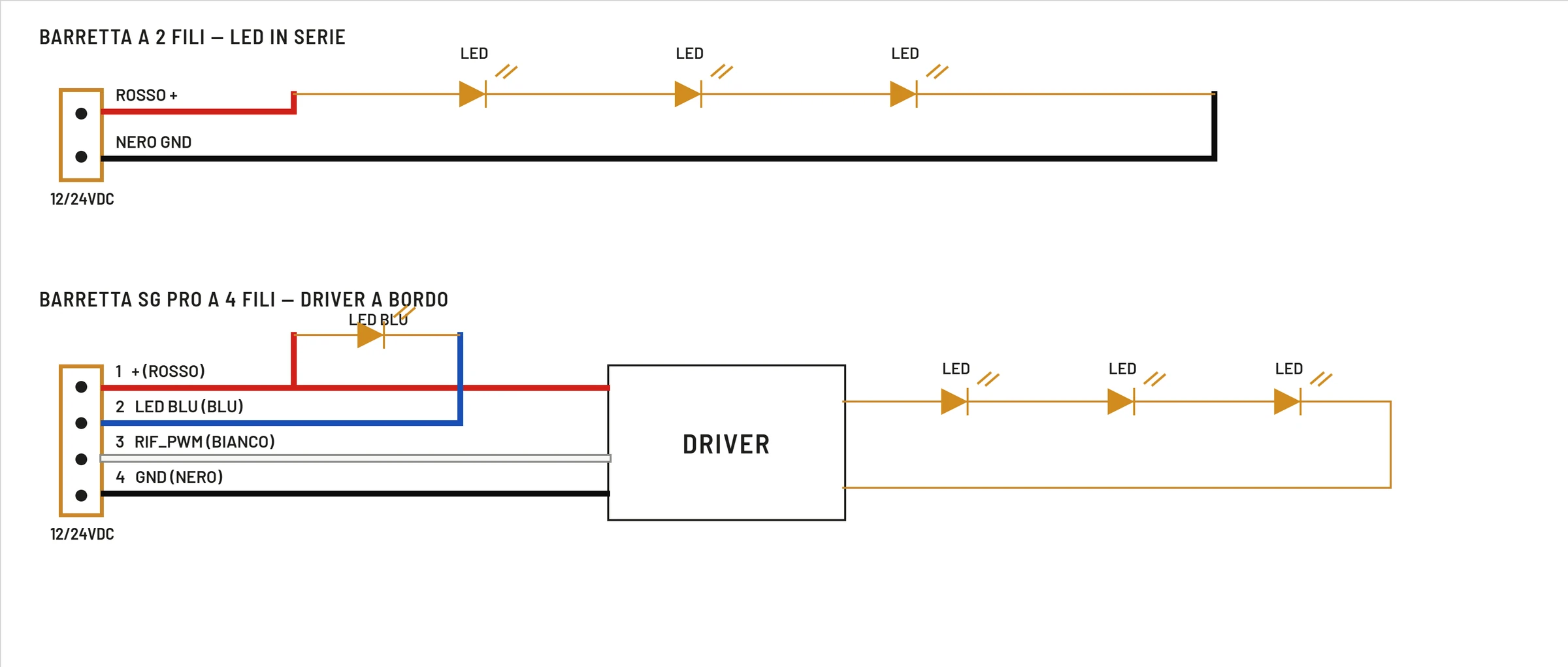
In 2-wire bars the SOL-LED directly powers the LED branch via positive and negative. In the 4-wire SG PRO bars there is an on-board driver: in addition to the power supply, the bar receives dedicated signals for regulation and for the blue LED.
For this reason it is not necessary to exchange the types of outputs: an SG PRO bar must be connected to the OUT-SG outputs, while a commercial 2-wire bar must be connected to the OUT outputs.
Optional accessories
The optional terminal of the night inspection button allows you to remote the INSP. command when required by the kit or the diagram supplied.
Sensors, remote buttons or other accessories must be connected only according to the wiring diagram supplied with the specific kit. Never apply unexpected voltages to the accessory terminals.