Complete Manual SOL-LED+
Printable version
Device version: SOL-LED+
Reference firmware: SOL-LED+ V9.8 B113 260826
Manual updated: 31/08/2026
Manual SOL-LED+
Welcome to the official documentation of the professional photoperiod controller SOL-LED+.
Index
Introduction
- Introduction to the system
- Fields of application
- Operating principle
Installation
- Security
- Panel, lights and terminals
- Installation
- First configuration
Programming
- Manual Program
- Personal Program
- Personal Program 2
- AstroGPS
- Automatic tables
Advanced features
- Maximum intensity and brightness
- Relay
- Night light
- Night inspection
- Energy Saving
- Use of rooms
Support
- Complete PDF manual
- Full downloadable PDF
- FAQ
- Troubleshooting
Technical information
- Technical Specifications
- CE conformity
- Warranty
- Comparison between SOL-LED Plus, SOL-LED and SOL-7000
Important information
The names of the functions, menus and programs shown in this documentation correspond to the words shown on the device display.
In case of differences between documentation and display, always refer to the indications displayed on the device.
Introduction
What is SOL-LED+
SOL-LED+ is a professional photoperiod regulator designed for the automatic management of LED lighting systems powered by very low direct voltage.
The device allows you to simulate in a natural way:
- dawn
- day
- sunset
- night light
The automatic management of the photoperiod allows you to reproduce seasonal variations in the duration of light during the year.
What is photoperiod for
A dawn-dusk control unit is used to automatically manage the lighting of the farm. Regulates switching on, off and light intensity progressively, avoiding sudden transitions between darkness and full light.
In ornithology, regular management of daylight hours can help accompany rest, moulting, preparation for reproduction and singing, always respecting the biological needs of the animals.
For those who breed live decoys, the gradual control of the light-dark cycle allows you to simulate the seasonal trend in a closed room and prepare the animals for the hunting period with more natural transitions. Use must always comply with current regulations and correct animal husbandry and welfare practices.
Main features
- Two rooms with separate programs and parameters
- Progressive simulation of sunrise and sunset
- Annual automatic programs
- Personalized programming
- AstroGPS mode
1 roomor2 roomsmode- Night light
- Energy saving
- Night inspection
- Permanent storage of settings
- Multilingual interface
Room management
SOL-LED+ manages two programmable outputs.
From the device menu you can choose the method of use:
2 rooms: the two outputs work as independent rooms;1 room: the second output follows the first, useful when you want to drive the same environment with both outputs, for example to distribute the power on two groups of LEDs.
In 2 rooms mode, each room can use:
- different programs
- different settings
- different program times
- different configurations
The two rooms share the same internal clock.
Operating philosophy
SOL-LED+ was designed to simplify photoperiod management.
The user can choose between:
- automatic programs
- personalized programs
- astronomical mode based on GPS coordinates
Once the initial configuration is completed, the device automatically manages the daily changes.
Applications
SOL-LED+ can be used in all environments where it is necessary to automatically control the photoperiod using LED lighting.
Examples:
- breeding
- maintenance
- reproduction
- greenhouses
- controlled environments
- experimental applications
Control panel
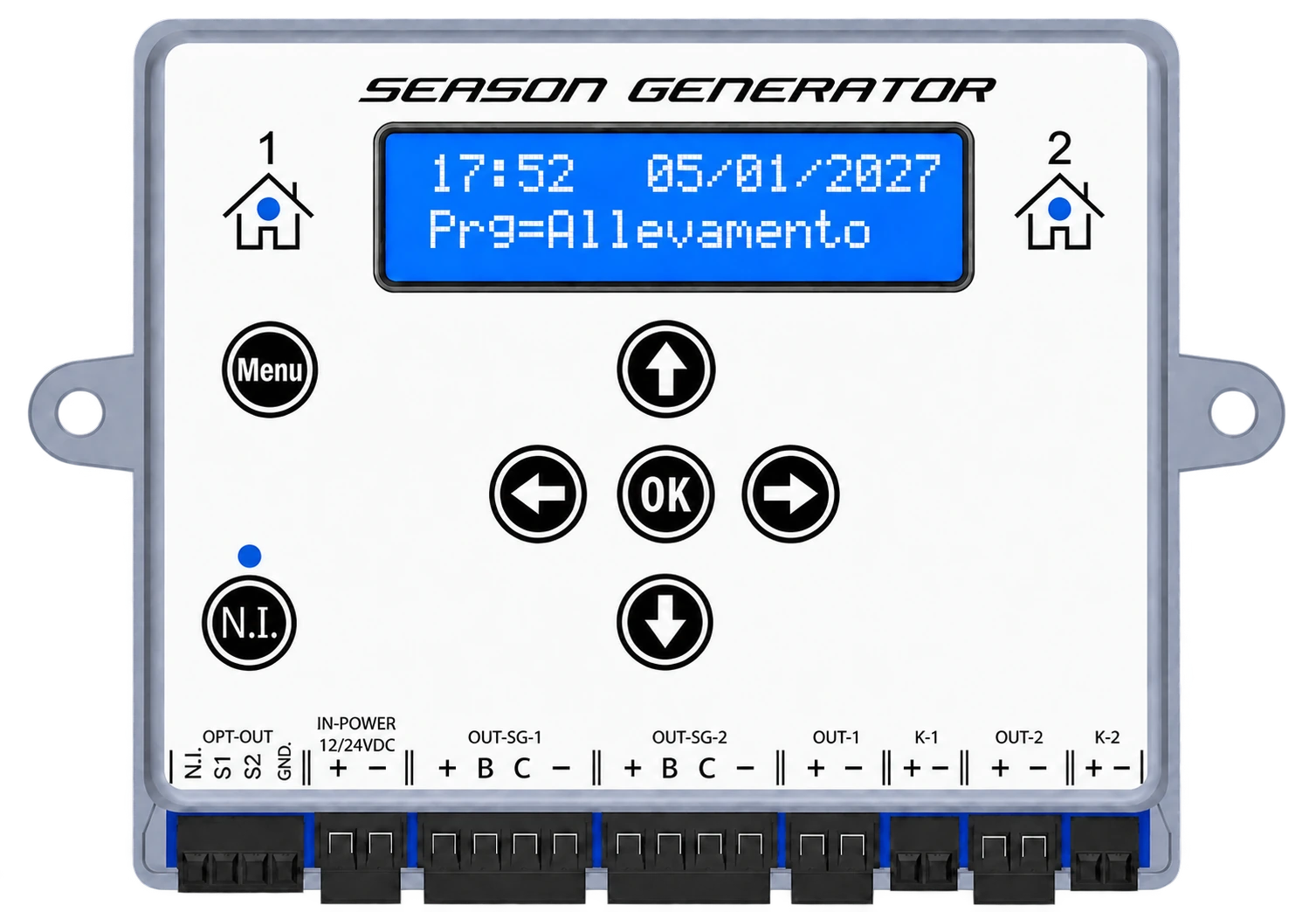
The main buttons are MENU, OK, directional arrows and INSP. for night inspection.
The front lights indicate the room reference 1, the room 2 and the status of the night inspection N.I..
To recognize the connection codes, consult the chapter Panel, Indicators and Terminals.
Security
General Information
Please read this manual carefully before installing or using SOL-LED+.
Incorrect installation can cause system malfunctions or damage to connected equipment.
Keep this manual for future reference.
Warnings
- Do not open the device.
- Do not modify the internal software of the device without authorization.
- Do not carry out unauthorized repairs.
- Do not exceed the declared electrical limits.
- Do not use the device in unsuitable environments.
- Install and wire the product only with the power supply disconnected.
Intended Use
SOL-LED+ is designed exclusively for the control of LED lighting systems powered by very low direct voltage.
Any use different from that intended is considered improper.
Power
SOL-LED+ must be powered exclusively with stabilized direct voltage between 12V DC and 24V DC.
Before switching on, check:
- correct polarity;
- supply voltage;
- correct size of the cables;
- compatibility of the connected system.
Load Limits
The device has two independent outputs/rooms. The maximum allowable current is 2,5 A per output.
Do not connect 230V lamps, inductive loads, unexpected external LED drivers or devices that are not compatible with the product specifications.
Water Protection
The device is not designed to be directly exposed to:
- rain;
- splashes of water;
- condensation;
- immersion.
Install the product in a dry and protected environment.
Water, splashes and baths
Control unit, power supply, LED bars, connectors and cables are not protected against water jets, splashes or immersion, unless a different IP rating is expressly indicated on the plate of the individual product.
On farms, position drinking troughs and bath trays so that water and splashes cannot reach electrical equipment, connections or LED bars. Do not install the bars under bathroom spots or in areas where water can drip onto the connectors.
If a component or cable gets wet:
- immediately remove the upstream power supply;
- do not touch connectors or electrical parts while they are wet;
- do not reactivate the system until it has been dried, checked and deemed suitable by qualified personnel.
Water and condensation can cause short circuits, corrosion, overheating and damage to equipment.
Load Compatibility
Always check that the connected load is compatible with the technical characteristics of the device.
The use of incompatible equipment can cause:
- abnormal functioning;
- performance reduction;
- permanent damage.
Note regarding power supply and electromagnetic compatibility
SOL-LED+ is a device powered exclusively by very low direct voltage (12-24V DC) and does not require any direct connection to the electrical network.
The device can be powered by batteries, accumulators or external power supplies compliant with the specifications indicated in this manual.When SOL-LED+ is installed using a power supply connected to the electrical network, the electromagnetic compatibility characteristics of the final system also depend on the power supply used, the wiring used and any other equipment possibly connected.
It is the installer's responsibility to verify that the power supply and the system in which the device is installed comply with applicable regulations and are suitable for the intended use environment.
The manufacturer is not responsible for any problems resulting from the use of non-compliant or incorrectly installed power supplies, wiring or external equipment.
Unauthorized Modifications
Any unauthorized hardware or software modification may compromise:
- safety;
- reliability;
- product conformity.
Unauthorized modifications will void the warranty.
Disposal
At the end of its useful life, the product must be disposed of in compliance with current regulations relating to electrical and electronic equipment.
Panel, Indicators and Terminals
This page helps you recognize the front controls, lights and all connections available on SOL-LED+.
The images are specific to the SOL-LED+ model. Connections must only be made with the device turned off and with the power disconnected.
General view
The following image shows the complete front panel, with displays, buttons, indicators of the two rooms and terminals arranged in the same order as the product.
SOL-LED+ can manage two separate programs, indicated as room 1 and room 2. The LEDs next to the room symbols indicate which room is displayed at that moment.
Front controls
| Command | Function |
|---|---|
Menu | enter the menu and move to the next item |
OK | confirms the displayed value and saves the change |
| up/down arrow | increases or decreases values and options |
| left/right arrow | move the editable field or change the displayed room |
N.I. | activates and manages the night inspection |
Front lights
| Spy | Meaning for the user |
|---|---|
home 1 | the screen and controls refer to room 1 |
home 2 | the screen and controls refer to room 2 |
spy N.I. | signals that night inspection is active |
In Room use -> 1 room mode, the outputs of room 2 follow the program of room 1. This mode allows you to distribute the lighting of the same room on two groups of LEDs.
Terminal summary
The table summarizes the terminals from left to right. The acronyms printed on the product remain identical in all languages; instead, the headings and explanations change, to make consultation clear even on the translated manual.
| Terminal | Pins | Function | Current |
|---|---|---|---|
| OPT-OUT | N.I. | remote night-inspection button input, in parallel with the N.I. panel button | — |
| OPT-OUT | S1 | room 1 brightness sensor input | — |
| OPT-OUT | S2 | room 2 brightness sensor input | — |
| OPT-OUT | GND. | common reference for the N.I., S1 and S2 signals | — |
| IN-POWER | + - | controller supply, regulated 12 VDC or 24 VDC | total of all outputs |
| OUT-SG-1 | + B C - | 4-wire SG PRO LED bars, room 1 program | max. 2.5 A |
| OUT-SG-2 | + B C - | 4-wire SG PRO LED bars, room 2 program | max. 2.5 A |
| OUT-1 | + - | commercial 2-wire LED bars or strips, room 1 | max. 2.5 A |
| OUT-2 | + - | commercial 2-wire LED bars or strips, room 2 | max. 2.5 A |
| K-1 | + - | relay-coil control at the PWM threshold, room 1 program | max. 100 mA |
| K-2 | + - | relay-coil control at the PWM threshold, room 2 program | max. 100 mA |
Power supply 12-24 V DC
SOL-LED+ does not connect directly to the mains. The 230 V AC network powers an external stabilized power supply; only the 12-24 V DC output of the power supply needs to reach IN-POWER.
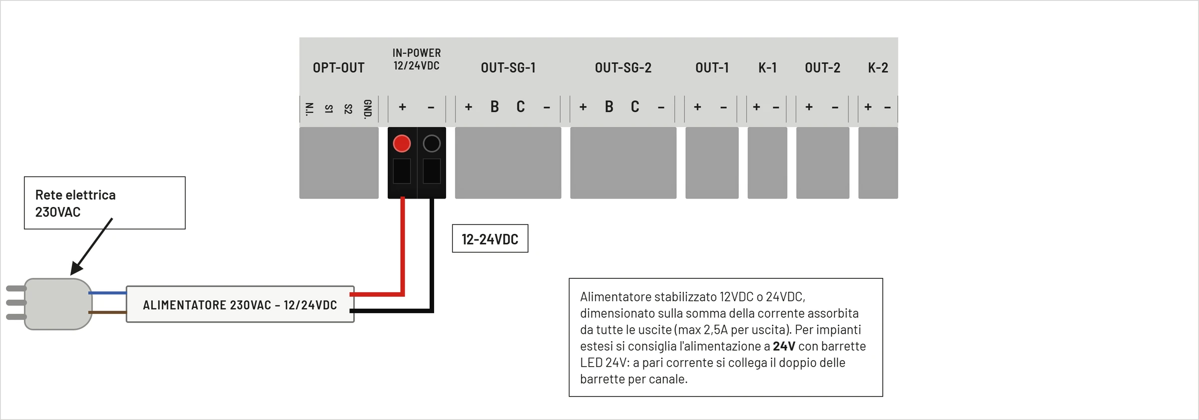
| Clamp | Function |
|---|---|
+ | positive power supply 12-24 V DC |
- | negative power supply |
The power supply must be stabilized and sized on the sum of the current absorbed by all the outputs used. For large systems it is advisable to work on 24 V with 24 V LED bars: with the same current it is possible to power a greater quantity of bars.
4-wire Season Generator PRO outputs
OUT-SG-1 follows the program of stanza 1; OUT-SG-2 follows the room 2 program. These outputs are dedicated to the 4-wire Season Generator PRO rods.
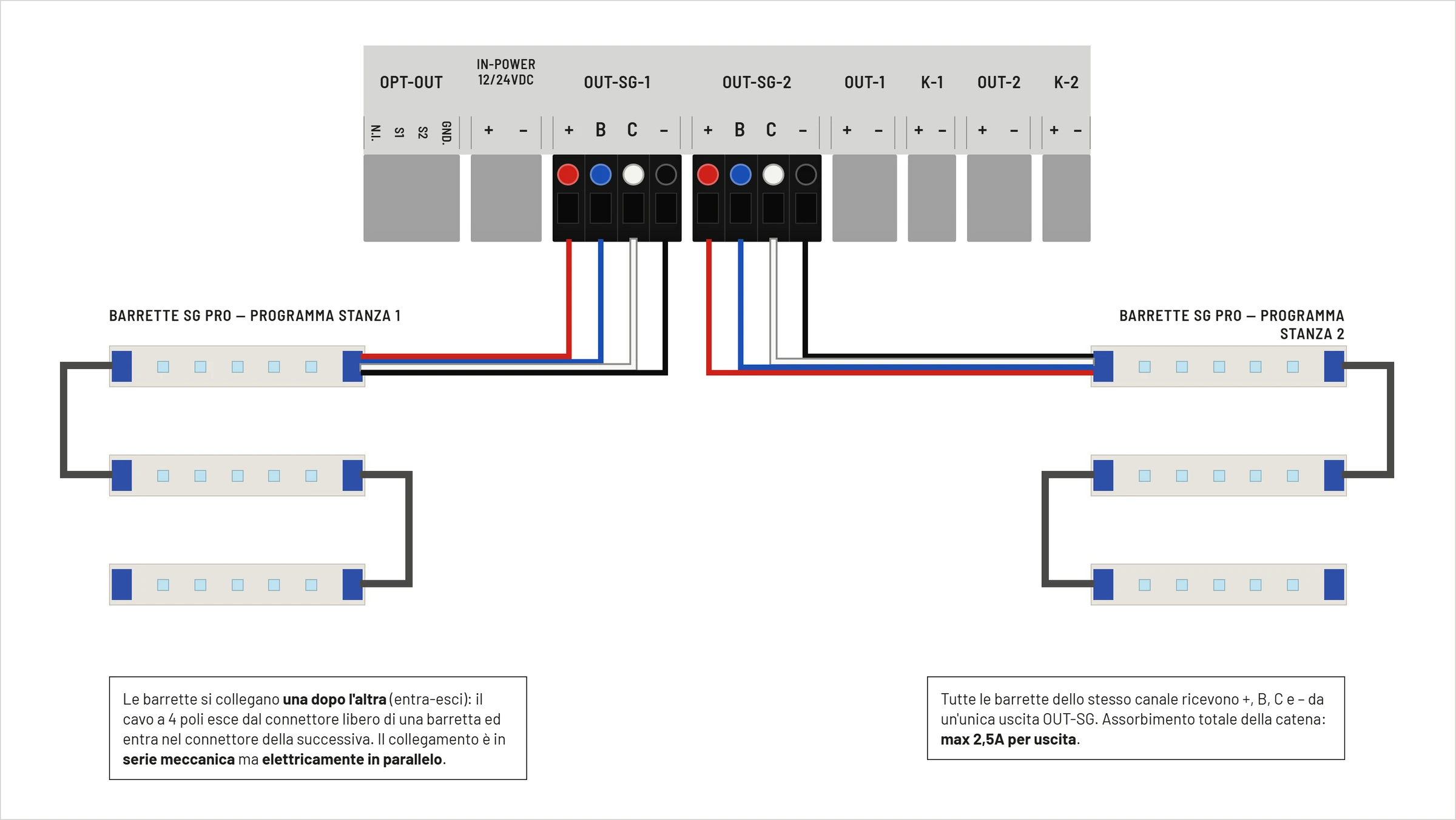
| Clamp | Conductor Color | Function | Limit |
|---|---|---|---|
+ | red | positive LED bar power supply | 2,5 A max |
B | blue | blue LED channel / night light | 100 mA max |
C | white | main PWM reference | 10 mA max |
- | black | common negative / GND | 2,5 A max |
The bars connect one after the other with the in-out system. The arrangement is a chain from a mechanical point of view, but all the bars of the same channel remain electrically in parallel. Total absorption must not exceed 2,5 A per output.
2-Wire Commercial LED Outputs
OUT-1 follows the program of stanza 1; The OUT-2 follows the room 2 program. These outputs power two-wire 12-24 V DC commercial LED bars or strips.
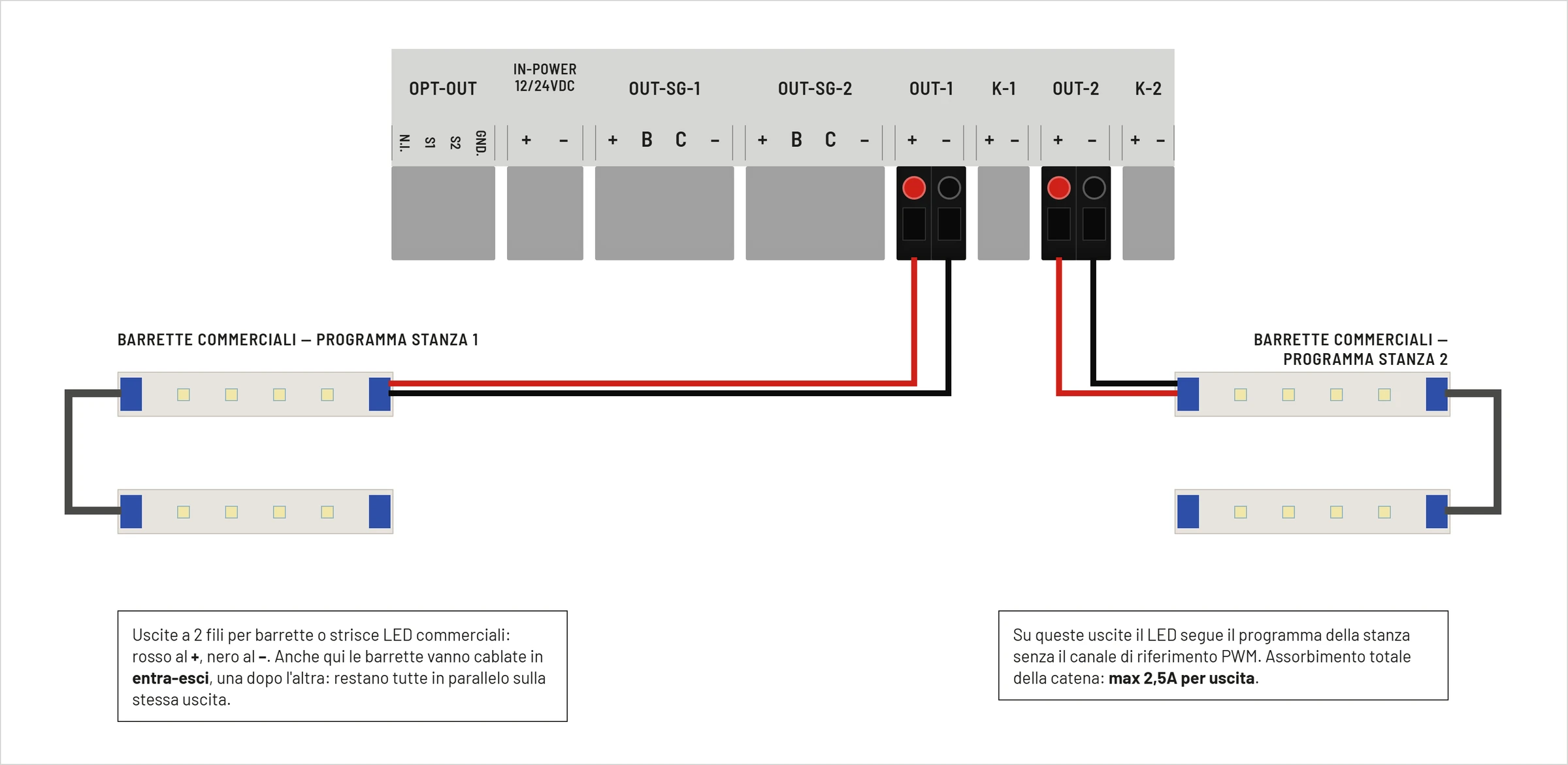
| Clamp | Typical Conductor Color | Function | Limit |
|---|---|---|---|
+ | red | positive LED bar power supply | 2,5 A max |
- | black | common negative | 2,5 A max |
Also in this case the bars can be connected in-out, as long as they remain electrically in parallel. Do not connect external drivers, 230 V lamps, or inductive loads to the LED outputs.
Difference between 2 and 4 wire bars
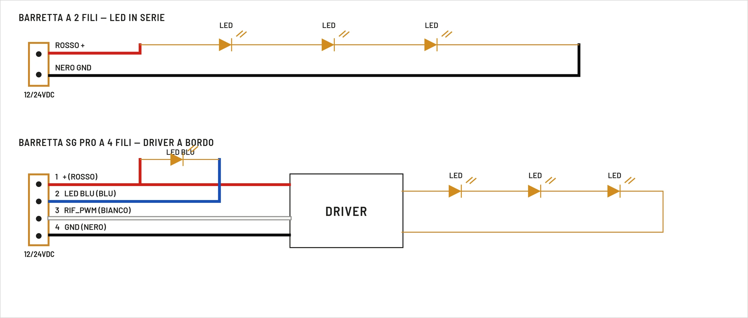
The two-wire rod receives positive and negative directly. The Season Generator PRO bar instead contains a driver and receives power, command for the blue LED, main PWM reference and ground.
Do not interchange the two types of output: the Season Generator PRO bars must be connected to OUT-SG, while the two-wire commercial bars must be connected to OUT.
Optional accessories OPT-OUT
The OPT-OUT clamp brings together the remote night inspection button and the two brightness sensors.
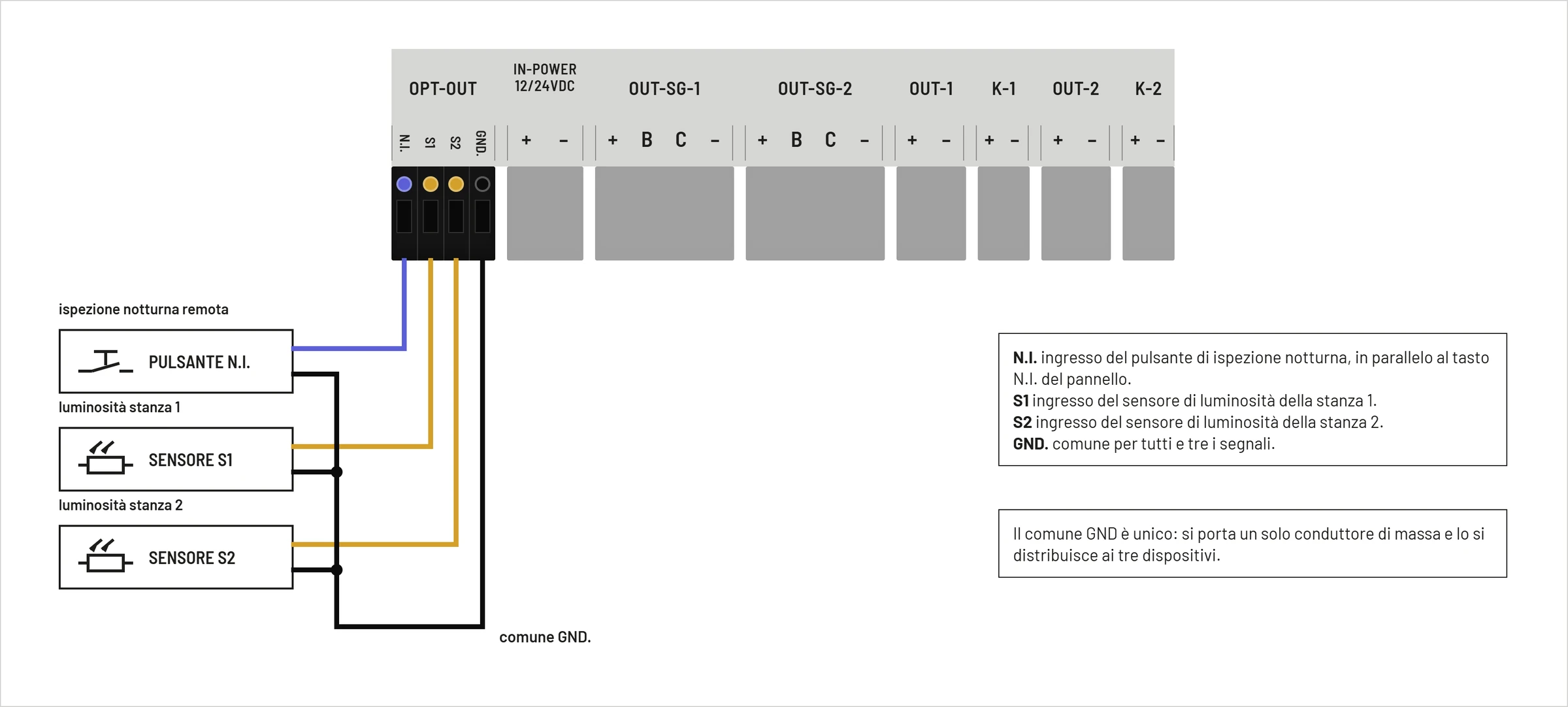
N.I.: remote button in parallel to the button on the panel;S1: room brightness sensor 1;S2: room brightness sensor 2;GND: common of the three signals.
The button must be a simple dry contact. Use only compatible sensors and do not apply external voltages to the N.I., S1, S2 or GND.
Releases K-1 and K-2
The K-1 and K-2 outputs exclusively control low direct voltage relay coils. They are not power contacts and must not directly power neon lights, lamps or the mains.
The voltage follows that of IN-POWER: with power supply to 12 V DC a coil is needed at 12 V DC; with power supply to 24 V DC you need a coil to 24 V DC. Maximum current is 100 mA per output.
The complete connection diagram is shown in the Relay chapter.
Shortcut shortcut
- bars Season Generator PRO:
OUT-SG-1orOUT-SG-2; - two-wire commercial LED bars:
OUT-1orOUT-2; - remote button: between
N.I.andGND; - room sensor 1: between
S1andGND; - room sensor 2: between
S2andGND; - room 1 relay coil:
K-1; - room 2 relay coil:
K-2.
Do not directly connect mains electricity, 230 V lamps, unforeseen LED drivers or final loads to the programmer terminals.
Installation
Introduction
Before proceeding with the installation, read this chapter carefully.
Verify that all connections are made with the power off.
To recognize the acronyms shown on the front graphics, consult the chapter Panel, Indicators and Terminals.
General scheme of the system
The diagram shows the complete structure of an installation with external power supply, two groups of Season Generator PRO bars, two groups of commercial LEDs, remote button, brightness sensors and relay for auxiliary lighting.
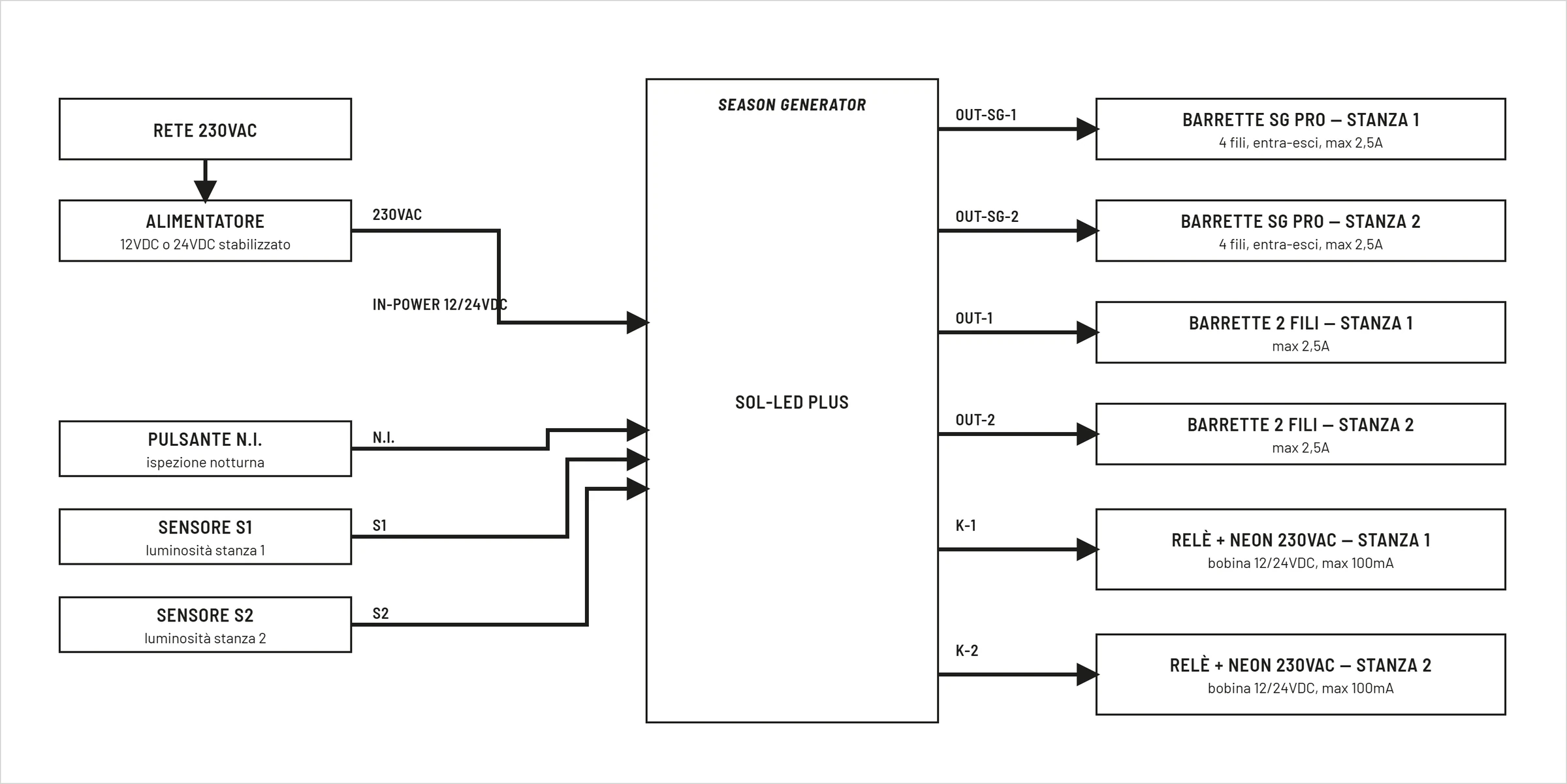
It is not necessary to use all outputs and accessories at the same time. Connect only those required by your system.
Package Contents
Check the presence of the following components:
- SOL-LED+
- User manual
- Any optional accessories
In case of damage due to transport, do not use the device.
Positioning
Install the device in a protected environment.
Avoid:
- direct exposure to the sun;
- excessive humidity;
- condensation;
- conductive powders;
- heat sources.
Ensure adequate ventilation.
Power
SOL-LED+ must be powered exclusively with stabilized direct voltage between:
- 12V DC
- 24V DC
Always check:
- correct polarity;
- correct tension;
- adequate power available.
Power connection
Connect the stabilized power supply to the IN-POWER 12/24VDC terminals, respecting the positive and negative polarity.
See the power diagram before connecting.
LED lighting connection
The LED outputs allow automatic lighting control through progressive brightness adjustment.
Before connecting, check:
- compatible voltage;
- current absorbed;
- correct polarity.
SeasonGenerator PRO Bar Link
The OUT-SG-1 and OUT-SG-2 outputs are dedicated to the SeasonGenerator PRO bars.
| Clamp | Function | Limit |
|---|---|---|
+ | positive LED bar power supply | 2,5 A max |
B | blue LED channel / night light | 100 mA max |
C | PWM sunrise/day/sunset reference | 10 mA max |
- | common negative | 2,5 A max |
Use only compatible modules.
See the Season Generator PRO output diagram.
2-Wire LED Bar Connection
The OUT-1 and OUT-2 outputs are dedicated to 2-wire commercial LED bars powered in DC.
| Clamp | Function | Limit |
|---|---|---|
+ | positive LED bar power supply | 2,5 A max |
- | common negative | 2,5 A max |
Do not connect external LED drivers, LED power supplies, 230V lamps or inductive loads.
For each room, choose the type of output suitable for the installed bar: OUT-SG for SeasonGenerator PRO bars or OUT for 2-wire LED bars.
See the two-wire LED output diagram.
Connection Optional Accessories
Optional accessories connect to the OPT-OUT and K terminals.
Main links:
- remote night inspection button: between
N.I.andGND; - room brightness sensor 1: between
S1andGND; - room brightness sensor 2: between
S2andGND; - room 1 relay coil: on
K-1 + -; - room 2 relay coil: on
K-2 + -.
For the button and sensors see the OPT-OUT diagram. For coils, see the Relay chapter.
Do not apply external voltage to N.I., S1 or S2. Do not connect the mains, lamps or final loads directly to the K-1 and K-2 terminals.
First start-up
After completing all connections:
- Power the device.
- Check that the display turns on.
- Check that the main screen is displayed correctly.
- Check the date and time.
- Proceed with the initial setup.
Check Installation
Before use check:
- correct functioning of the display;
- correct button response;
- correct activation of the outputs;
- correct setting of date and time.
Problems at first startup
If the device does not turn on:
- check the power supply;
- check the polarity;
- check the power supply fuse and the upstream protections;
- check the wiring.
For further information, see the Troubleshooting chapter.
First Configuration
Introduction
When you turn it on for the first time, it is advisable to immediately check the main system settings.
Correct initial configuration guarantees the correct functioning of all the automatic functions of the device.
Recommended Operations
After the first ignition, check in this order:
- Language
- Date
- Now
- Use of rooms
- Selected room
- Intensity
- Program used
- Sunrise duration
- Sunset duration
Language setting
Real route:
MENU -> Language
Procedure:
- Press MENU.
- Select
Language. - Press
ENTER. - Select the desired language.
- Press
ENTERto confirm.
Your changes are automatically saved.
Date and Time setting
Correct setting of the date and time is essential for the operation of the automatic programs.
Real route:
MENU -> Modify / Date / Time
Procedure:
- Press MENU.
- Select
Modify/Date / Time. - Press
ENTER. - Set current date.
- Set current time.
- Confirm with
ENTER.
Room selection
SOL-LED+ manages two rooms with separate programs and parameters.
Before changing any parameter, always check the currently selected room.
Many settings are stored separately for each room.
Date and time are shared: the control unit uses a single time reference and aligns room 2 with room 1.
Setting Room use
Real route:
MENU -> Device temp -> MENU -> Room use
Available values:
1 room2 rooms
With 2 rooms, the two outputs maintain separate programs and parameters.
With 1 room, room 2 copies room 1: day light, night light, inspection ramp and relay status follow room 1.
Use 1 room when you don't need different programs and you want to use both outputs for the same environment, for example to distribute the power across two groups of LEDs.
The default value is 2 rooms.
Intensity' setting
Real route:
MENU -> Intensity'
The screen allows you to choose how to limit the main light of the active room:
Fixed: use only one maximum limit;Seasonal: uses a minimum and maximum limit calculating the value of the day based on the photoperiod.
Real limits of percentage values:
- minimum:
10 % - maximum:
100 % - maximum limit default value:
80 %
In Seasonal mode, Season Min cannot exceed Season Max.
Program Selection
After configuring the date and time you can choose the desired program.
Real route:
MENU -> Use Program
For further information, see the Programs chapter.
Sunrise and sunset setting
It is advisable to check:
- dawn duration;
- sunset duration.
Higher values produce smoother transitions.
Lower values produce faster changes.
System Verification
Once the initial configuration is complete, check:
- correct display visualization;
- correct functioning of the buttons;
- correct selection of the room;
- correct program selected;
- correct functioning of the outputs.
Configuration Complete
Once the initial configuration is completed the device is ready for normal use.
The settings are automatically saved and remain stored even in the event of a power failure.
Programs
Introduction
SOL-LED+ manages the photoperiod through programs selectable from the Use Program menu.
The control unit manages two rooms with separate programs and parameters. The active room may have a different program than the other room; the room change is managed by the dedicated button and by the room LED signaling. The clock is unique: in 1 room mode, room 2 is aligned with room 1.
If Room use is set to 1 room, the operational selection remains on room 1 and the second output copies the first. Room 2 programs become relevant again when you move Room use back to 2 rooms.
The names shown in this chapter are those shown on the display.
Actual menu path
Route:
MENU -> Use Program
Screens displayed:
Use ProgramPrg:
With the UP and DOWN keys you scroll the list of programs. With ENTER you confirm the displayed program.
With MENU, from the Use Program screen, you go to the next screen of the main menu.
Program list
The available programs are:
The names of the preloaded tables should not be interpreted as an exclusive restriction to the indicated species. They are practical names assigned to different light profiles: each table has its own seasonal trend, with minimum and maximum length of the day, growth and reduction of hours, sunrise and sunset times and ramp progression. For this reason, a table called, for example, Song thrush, REDWING, Fieldfare, Canaries or Crest Agi can also be used in different situations, when the light profile better corresponds to the objective of the farmer or user.
| Display Name | Usage |
|---|---|
Custom2 | personalized program with start/end date |
Personal | personalized program with daily variation + / - minutes |
Standard | general light profile, useful when there are multiple needs or multiple species in the same room |
Song thrush | preloaded light profile identified with this name |
REDWING | preloaded light profile identified with this name |
Skylark | preloaded light profile identified with this name |
Fieldfare | preloaded light profile identified with this name |
Breeding | preloaded light profile oriented towards breeding |
Finches | preloaded light profile identified with this name |
Canaries | preloaded light profile identified with this name |
Crest Agi | preloaded light profile identified with this name |
AstroGPS Timer | astronomical program from coordinates |
Manual | program with fixed times set by the user |
The programs listed can be selected directly from the Prg: menu.
Program Manual
The Manual program uses fixed times set by the user. It does not apply daily increments and does not use an annual table.
When you confirm Prg: Manual, the display shows the sequence:
Sunrise beginSunset beginSunrise durationSunset duration
Use Manual when you want to keep the same on and off times every day.
Programs with preloaded table
Programs with a preloaded table use sunrise and sunset values already stored in the device.
On the Season Generator website it is possible to see the behavior of the main tables and the times they represent day by day:
- Standard Table
- Bottaccio Table
- Sassello Table
- Lark Table
- Finches Table
- Canaries Table
- Agi and Crest Table
To advance or postpone the times in the table compared to those displayed, simply move the programmer date forwards or backwards. In this way the table also moves automatically and the user can adapt the period of greatest light to their needs.
For these programs the control unit calculates the daily times from the preloaded table and allows you to configure:
Sunrise durationSunset duration
Both parameters are expressed in minutes and have real limits:
- minimum:
1 - maximum:
100
Program Personal
The Personal program does not use a default annual table. The user sets initial times and daily variations.
When you confirm Prg: Personal, the display shows the sequence:
Reset day/Count :Sunrise beginSunset begin+/-min Sunrise+/-min SunsetHow many days?Sunrise durationSunset duration
The detailed operation is described in chapter Tabella Personal.
Program Custom2
The Custom2 program automatically calculates a progression between an initial photoperiod and a final photoperiod.
When you confirm Prg: Custom2, the display shows the sequence:
Start date phoSunrise todaySunset todayEnd date photoSunrise endSunset endSunrise durationSunset duration
The detailed operation is described in the Tabella Personal 2 chapter.
Program AstroGPS TimerThe AstroGPS Timer program calculates times using the Controller place, Simulated place, UTC: offset, and Twilight: setting.
When you confirm Prg: AstroGPS Timer, the display shows the sequence:
Controller place/Lat:Controller place/Long:Controller place/UTC:Simulated place/Lat:Simulated place/Long:Twilight:
The detailed operation is described in chapter AstroGPS.
Common parameters after program selection
For Manual, for the internal tables, for Personal and for Custom2, the control unit uses the parameters:
Sunrise durationSunset duration
These parameters regulate the duration of the on and off ramp.
For AstroGPS Timer, ramps are calculated based on astronomical events derived from Controller place, Simulated place, and Twilight:.
Personal Table
Introduction
In the menu the Personal Table corresponds to the Personal program.
This mode allows you to set an initial photoperiod and automatically modify it day by day via the +/-min Sunrise, +/-min Sunset and How many days? parameters.
Actual menu path
Route:
MENU -> Use Program -> Prg: Personal -> ENTER
Screens displayed:
Reset day/Count :Sunrise beginSunset begin+/-min Sunrise+/-min SunsetHow many days?Sunrise durationSunset duration
Reset day
The Reset day screen allows you to reset the day count used by the Personal Table.
Displayed values:
YESNO
If you confirm YES, the control unit resets the day counter of the active room.
Use reset when you want to restart the program from day one.
Sunrise begin
Set the initial sunrise time.
Format:
HH:MM
Real limits:
- hours:
00-23 - minutes:
00-59
Commands:
LEFTincreases hours;UPincreases minutes;ENTERconfirm and move to the next screen.
Sunset begin
Set the initial sunset time.
Format:
HH:MM
Real limits:
- hours:
00-23 - minutes:
00-59
Commands:
LEFTincreases hours;UPincreases minutes;ENTERconfirms and goes to the next screen.
+/-min Sunrise
Sets the daily variation of sunrise, in minutes.
Real limits:
- minimum:
-100 - maximum:
100
Real behavior:
- positive value: dawn is brought forward day by day;
- negative value: sunrise is postponed day by day;
- value
0: sunrise remains unchanged.
The control unit applies the variation once a day until the day counter is less than How many days?.
+/-min Sunset
Set the daily sunset variation, in minutes.
Real limits:
- minimum:
-100 - maximum:
100
Real behavior:
- positive value: sunset is postponed day by day;
- negative value: sunset is brought forward day by day;
- value
0: the sunset remains unchanged.
How many days?
Set how many days to apply the daily changes for.
Real limits:
- minimum:
0 - maximum:
365
If the value is 0, the control unit does not apply daily variations to the photoperiod.
Sunrise duration
Set the dawn ramp duration.
Real limits:
- minimum:
1minute - maximum:
100minutes
Sunset duration
Set the duration of the sunset ramp.
Real limits:
- minimum:
1minute - maximum:
100minutes
Automatic operation
Every day the control unit:
- compare the RTC day with the day recorded for the table;
- increment the counter if
cntOfDaysis less thanHow many days?; - update
Sunrise beginusing+/-min Sunrise; - update
Sunset beginusing+/-min Sunset; - save the parameters in memory.
The schedules also handle passing past 00:00 and 23:59.
Personal Table 2
Introduction
In the menu, Personal Table 2 corresponds to the Custom2 program.
Custom2 automatically calculates daily times by interpolating between:
- sunrise and sunset of the initial day;
- sunrise and sunset of the final date.
The calculation occurs in minutes, is updated based on the device date and rounds the interpolation to the nearest minute.
Actual menu path
Route:
MENU -> Use Program -> Prg: Custom2 -> ENTER
Screens displayed:
Start date phoSunrise todaySunset todayEnd date photoSunrise endSunset endSunrise durationSunset duration
Start date pho
The starting date is not entered manually.
The display shows the current date and, when you press ENTER, the control unit copies:
- RTC day;
- RTC month;
- RTC year;
in the program start parameters.
To change the starting date of Custom2, first correct the device date in the Modify / Date / Time menu.
Sunrise today
Set the sunrise time of the starting day.
Format:
HH:MM
Real limits:
- hours:
00-23 - minutes:
00-59
Commands:
LEFTincreases hours;UPincreases minutes;ENTERconfirms.
Sunset today
Set the sunset time of the starting day.
Format:
HH:MM
Real limits:
- hours:
00-23 - minutes:
00-59
Commands:
LEFTincreases hours;UPincreases minutes;ENTERconfirms.
End date photo
Set the end date of the photoperiod.
The control unit initially proposes the day following the initial date.
Real commands:
DOWNincrements day;RIGHTincrements the month;MENUincrements the year;ENTERconfirms.
Real limits:
- day:
01-31, then corrected based on the month; - month:
01-12; - year:
2018-2099.
The day calculation uses non-leap months: February is limited to 28 days.
Real validation:
- the final date must be later than the initial date;
- the maximum distance accepted is
363days; - if the date is not valid the display shows
Date errorandPress ENTER.
Sunrise end
Set the sunrise time to reach the final date.
Format:
HH:MM
Real limits:
- hours:
00-23 - minutes:
00-59
Sunset end
Set the sunset time to reach the final date.
Format:
HH:MM
Real limits:
- hours:
00-23 - minutes:
00-59
Sunrise duration
Set the dawn ramp duration.
Real limits:
- minimum:
1minute - maximum:
100minutes
Sunset duration
Set the duration of the sunset ramp.
Real limits:
- minimum:
1minute - maximum:
100minutes
Real automatic calculation
The control unit calculates, for each day:
- absolute starting day;
- absolute final day;
- current RTC day;
- position of the current day between start and end;
- Sunrise and sunset interpolated between the initial and final values, rounded to the nearest minute.
If the device date is before the beginning, the control unit uses the first day. If the date exceeds the end date, use the end values.
The result is limited between 00:00 and 23:59.In the total light information screens, the device also adds Sunset duration to the time between sunrise and sunset. The total displayed is limited to 23:59.
Default values
When reloading the default parameters, the control unit sets:
- start date:
01/01/2026; - initial dawn:
08:00; - initial sunset:
18:00; - end date:
31/12/2026; - final dawn:
07:30; - final sunset:
19:00.
These values are internal defaults and can be changed by user programming.
AstroGPS
Introduction
On the display the astronomical mode is shown as AstroGPS Timer.
AstroGPS Timer calculates daily times using:
- coordinates of
Controller place; - offset
UTC:ofController place; - coordinates of
Simulated place; - status of the
Twilight:parameter.
Times are recalculated based on the RTC date.
The coordinates are divided into two groups:
Controller place: real position of the control unit, used to locate the local solar noon;Simulated place: position to simulate, used to obtain day length and twilight duration.
Actual menu path
Route:
MENU -> Use Program -> Prg: AstroGPS Timer -> ENTER
Screens displayed:
Controller place/Lat:Controller place/Long:Controller place/UTC:Simulated place/Lat:Simulated place/Long:Twilight:
Controller place
The first part of the configuration sets the real location of the control unit.
Screens displayed:
Controller place/Lat:Controller place/Long:Controller place/UTC:
The control unit uses these coordinates and UTC: to calculate local sunrise and sunset and derive solar noon.
Lat:
Set the latitude in hundredths of a degree.
The Lat: screen appears under both Controller place and Simulated place.
Display format:
N+DDD.DD or S-DDD.DD
Real limits:
- minimum:
S-066.00 - maximum:
N+066.00
Real commands:
LEFTandRIGHTmove the cursor;UPincreases the selected value;DOWNdecreases the selected value;- on the position of the sign,
UPorDOWNreverse North/South; ENTERconfirms and goes to the next screen of the current block.
Long:
Set the longitude in hundredths of a degree.
The Long: screen appears under both Controller place and Simulated place.
Display format:
E+DDD.DD or O-DDD.DD
On the display the letter O indicates West longitude.
Real limits:
- minimum:
O-180.00 - maximum:
E+180.00
Real commands:
LEFTandRIGHTmove the cursor;UPincreases the selected value;DOWNdecreases the selected value;- on the sign position,
UPorDOWNreverse East/West; ENTERconfirm and move to the next screen. FromController placeit goes toUTC:, fromSimulated placeit goes toTwilight:.
UTC:
Sets the local offset from UTC.
Display format:
+HH:MM or -HH:MM
Real limits:
- minimum:
-12:00 - maximum:
+14:00
Real commands:
LEFTincreases by 60 minutes;RIGHTdecreases by 60 minutes;UPincreases by 15 minutes;DOWNdecreases by 15 minutes;ENTERconfirm and move toSimulated place/Lat:.
Simulated place
The second part of the configuration sets the location to simulate.
Screens displayed:
Simulated place/Lat:Simulated place/Long:
The limits and commands are the same as Lat: and Long: of Controller place.
In the calculation, the control unit obtains the length of the day and the duration of the twilight periods from the Simulated place. These durations are then centered on solar noon calculated by the Controller place.
The display does not expose a separate UTC: parameter for the Simulated place.
Twilight:The Twilight: screen allows you to enable or disable the use of twilight.
Actual display values:
EnabledDisabled
Real commands:
UPtoggles the value;DOWNtoggles the value;ENTERsave and return to the main page.
When Twilight: is confirmed, the control unit uses civil twilight.
If Twilight: is disabled, the device does not use the Start Crack and End Crack traits: the start of light coincides with Sunrise and the end of light with Sunset. Base ramps start at 1 minute, while Astro transition maintains the variation for 30 minutes after Sunrise and 30 minutes before Sunset.
If Twilight: is enabled, the device uses the onset of civil twilight as the onset of sunrise and ramps up to the calculated sunrise.
Type of twilight
In this revision the user menu manages civil twilight.
There is no user choice between nautical or astronomical twilight.
Real ramp behavior AstroGPS
With Twilight: enabled, the control unit:
- calculate sunrise and sunset of
Controller place; - obtains local solar noon from
Controller place; - calculate day duration and twilight duration of the
Simulated place; - centers the duration of the simulated day on the local noon of the control unit;
- calculate
Crack Start,Sunrise,SunsetandCrack End; - bring the light from
0to the twilight level betweenIniz CrepandDawn; - brings the light from twilight level to maximum level in the 30 minutes following
Dawn; - maintains the maximum level during the day;
- reduces light in the 30 minutes before
Sunset; - Bring the light from the twilight level to
0betweenSunsetandEnd Crep.
With Twilight: disabled, the control unit uses dawn and dusk without extending the ramps to dusk; 30 minute Astro transitions around sunrise and sunset remain.
On the main page, when the active program is AstroGPS Timer, the display also shows dedicated information screens:
Sunrise/Sunset;Start Crack/End Crack;Total light hr/Today.
Default values
When reloading the default parameters, the control unit sets:
Controller placelatitude:28.29;Controller placelongitude:-16.63;Controller placeUTC offset:0;Simulated placelatitude:28.29;Simulated placelongitude:-16.63;- twilight type:
Civil; Twilight:enabled.
Negative longitude is displayed as West.
An initial configuration may include room 1 on AstroGPS Timer, Controller place set to the actual installation position and Simulated place set to the place whose light cycle you want to reproduce.
Maximum intensity and brightness
Introduction
On the display the function is shown as:
Intensity'
This feature limits the maximum level reached by the main active room light.
The seasonal mode allows you to automatically vary, over the course of the season, not only the duration of the photoperiod but also the maximum intensity of the lighting.
In nature, the change of seasons does not only affect the hours of light: in periods with shorter days the light intensity can also be lower than in periods with long days and there is greater lighting.
By setting a minimum value and a maximum value, the control unit calculates the most suitable limit day by day. The variation occurs progressively together with the light program, without sudden changes.
On the display the item to search for is Intensity'.
Actual menu path
Route:
MENU -> Intensity'
In the real menu loop, Intensity' comes after Use Program and before Room relay.
The first screen allows you to choose:
FixedSeasonal
With UP or DOWN you switch from one mode to the other. With ENTER you enter the values of the chosen mode.
Fixed mode
In Fixed mode, the controller uses only one maximum limit.
Displayed screen:
Intensity'
Real values:
| Parameter | Value |
|---|---|
| Minimum | 10 % |
| Maximum | 100 % |
| Default value | 80 % |
Real commands:
UPincreases the value;DOWNdecreases the value;ENTERsave and return to the main page;MENUmoves to the next menu item.
Seasonal mode
In Seasonal mode, the controller automatically calculates the day limit using the photoperiod of the active program.
Screens displayed:
Mini seasonMax season
Real values:
| Parameter | Value |
|---|---|
Mid season | 10 % - 100 % |
Max season | 10 % - 100 % |
Min season cannot exceed Max season. If the maximum is lowered below the minimum, the control unit automatically lowers the minimum as well.
The control unit uses values closer to Min season in periods with a shorter photoperiod and values closer to Max season in periods with a longer photoperiod.
Example:
- minimum period:
40 %; - maximum period:
100 %.
During the growing phase of the season, the maximum value gradually increases day by day. During the decreasing phase, the process occurs in reverse.
Information screens
When the Seasonal mode is active and the program allows profile calculation, the following may appear on the main page:
PWM startPWM todayPWM end
These screens indicate the level calculated at the beginning of the profile, the level of the current day and the final level.
Effect on operation
Intensity' does not change sunrise and sunset times.
The control unit calculates the light ramp of the active program and then limits the main light level to the value allowed by the chosen mode.
If for a certain day the calculated value is 65 %, during dawn the light will progressively rise up to 65 %. During the period of full light it will remain at that level and, at sunset, it will gradually decrease from that value.
Example in Fixed mode:
- active program at
100 %; Intensity'set to80 %;- main light output limited to
80 %.
Use with 1 room
With Room use -> 1 room, room 2 copies the level of room 1. In this mode the operating limit to be considered is that of room 1.
Relay
Introduction
SOL-LED+ was created above all to control the LED bars installed near the cages. These bars allow you to create dawn, daylight, dusk and night light in a gradual and localized way.
In some environments, however, the bars near the cages are not enough to completely illuminate the room. It may therefore be useful to also turn on one or more neon lights, ceiling lights or other lamps intended for the general lighting of the room.
The K-1 and K-2 outputs allow this result to be obtained via an external relay:
K-1follows the main light of room 1;K-2follows the main light of room 2;- each output powers only the low voltage coil of its own relay;
- the power contacts of the relay turn the neon lights or lamps in the room on and off.
In this way SOL-LED+ continues to adjust the LED bars for smooth transitions and, when the light has reached the set level, it can also automatically turn on the general lighting.
On the display, relay management is shown with the screens:
Room relayRelay PWM ON
The relay is managed separately for each room.
Actual menu path
Route:
MENU -> Room relay
In the real menu loop, Room relay comes after Intensity' and before Energy Saving.
Screens displayed:
Room relayRelay PWM ON
Room relay
Enable or disable the active room relay.
Actual display values:
YESNO
Real commands:
UPsetsYES;DOWNsetsNO;ENTERconfirms.
If Room relay is NO, the relay remains off.
If Room relay is YES, the display changes to the Relay PWM ON screen.
Relay PWM ON
Sets the percentage threshold of the main light PWM at which the relay must activate.
Real limits:
- minimum:
0 % - maximum:
100 %
Default value:
80 %
Real commands:
UPincreases the value;DOWNdecreases the value;ENTERsave and return to the main page.
Real behavior of the relay
The relay does not use a dedicated time slot.
The control unit calculates the PWM of the main light in the room and then:
- if
Room relayisNO, forces the relay off; - if there is a
ALLARME_NTCthermal alarm, forces the relay off; - if
Room relayisYESand the PWM percentage is greater than or equal toRelay PWM ON, turns on the relay; - if the PWM percentage is less than
Relay PWM ON, it turns off the relay.
The firmware uses a single configurable threshold: the relay turns on when Relay PWM ON is reached and turns off when the value falls below the same threshold. There is no second switch-off threshold.
The threshold is compared to the PWM of the main light, not to the Night Light.
In Room use -> 1 room mode, the room 2 relay follows the calculated state for room 1.
Practical example with 80% threshold
Suppose we set Relay PWM ON to 80 %.
- At the beginning of dawn the LED bars light up at low intensity and gradually increase.
- As long as the main light remains under the
80 %, the relay remains open and the neon remains off. - When the ramp reaches
80 %, SOL-LED+ energizes the relay coil. - The relay closes the power contacts and turns on the neon or lamps that illuminate the room.5. During sunset the reverse process occurs: when the light drops below the
80 %, the coil is de-powered, the contacts open and the general lighting turns off.
The LED bars can thus continue the final part of the sunset on their own, avoiding the sudden switching off of all the lights in the room.
Relay coil connection
The K-1 and K-2 outputs are not power contacts. They are low voltage DC outputs to power the coil of an external relay, with a maximum current of 100 mA per output.
The available voltage is the same as the device power supply:
- power supply SOL-LED+ to
12 V DC: use a12 V DCrelay coil; - power supply SOL-LED+ to
24 V DC: use a24 V DCrelay coil.
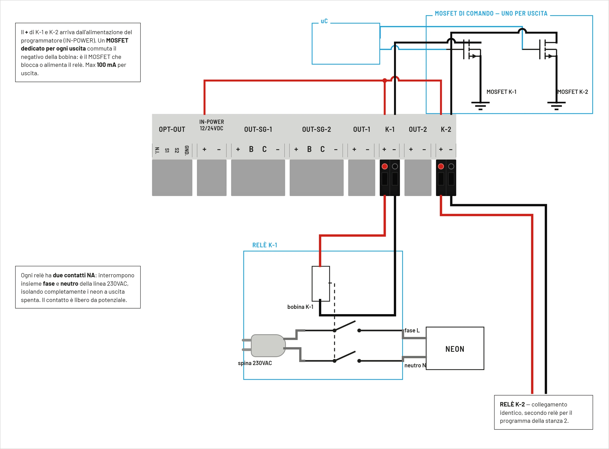
The relay has two electrically separated parts:
- control side: the coil to
12 V DCor24 V DC, connected toK-1orK-2; - power side: the contacts that connect and disconnect the power supply of the neon, ceiling light or lamps.
The diagram shows an example with an external bipolar relay. On the power side, a cable with plug carries the power from the mains socket to the relay contacts; a second cable comes out of the contacts and reaches the neon or the lamps in the room. When the coil is energized, the normally open contacts close and the load turns on.
The chosen relay must have:
- coil with the same supply voltage as SOL-LED+;
- coil absorption not exceeding
100 mA; - contacts sized for voltage, current and type of connected load;
- suitable insulation between low voltage coil and mains contacts.
The final load must be connected to the external relay contacts, not directly to K-1 or K-2. Connections to the electrical network must be carried out by qualified personnel.
Never connect the 230 V AC mains to the K-1 or K-2 terminals. These terminals power exclusively the low voltage coil of the relay. Plug, mains cable, power contacts and neon connection must be made and protected according to the regulations of the electrical system.
Effect during sunrise and sunset
During the dawn ramp, the PWM increases progressively. The relay activates when the ramp reaches the Relay PWM ON threshold.
During the sunset ramp, the PWM progressively decreases. The relay deactivates when the ramp drops below the Relay PWM ON threshold.
Compatibility with programs
The behavior of the relay depends on the PWM generated by the active program.
It is therefore applicable with:
ManualPersonalCustom2AstroGPS Timer- internal tables like
Standard,Song thrush,REDWING,Skylark,Fieldfare,Breeding,Finches,Canaries,Crest Agi
Night Light
What is it for
The Night Light function automatically maintains a very low brightness when the daily program enters the night phase.
It can be useful when you don't want to leave the environment completely dark and want to maintain a weak light reference. It must not transform the night into a full light phase: normally a low value is set, sufficient for the purpose but clearly distinct from daylight.
On compatible Season Generator PRO bars the function uses the channel dedicated to the night light. The adjustment is separate from the main light and is managed automatically by the room program.
On the display the function is shown as Night Light.
Actual menu path
Route:
MENU -> Night Light
In the real menu loop, Night Light comes after Energy Saving and before Inspection time.
Displayed screen:
Night Light
Configurable parameter
The screen shows:
OFF, if the value is0;- a percentage, if the value is greater than
0.
Real limits:
- minimum:
0 %(OFF) - maximum:
50 %
Default value:
0 %(OFF)
Real commands:
UPincreases the value;DOWNdecreases the value;ENTERsave and return to the main page;MENUgoes to theInspection timescreen.
Real behavior
The controller calculates the maximum room level from Intensity' and then calculates Night Light as a percentage of that level.
During the day the main light prevails. When the main light is at zero, the controller can gradually raise the night light to the set level. When the next daytime phase starts, the device manages the transition from night light to the normal dawn ramp.
If the value is OFF, at the end of sunset the room is brought to the darkness foreseen by the program.
Practical example
With Intensity' set to 80 % and Night Light to 10 %, the nighttime level is taken from the maximum configured for that room. Changing the maximum intensity therefore also changes the actual level of the night light.
Always start from low values and observe the real result in the environment. Increase the value only if the light reference is not sufficient.
Difference from night inspection
The Night Light is automatic and can remain active throughout the night phase foreseen by the program.
The Night Inspection, on the other hand, is a temporary command used to enter the room and see for the time necessary for the visit. At the end it must be deactivated to return control to the main program.
Interaction with Energy Saving
The Night Light is inhibited when the device activates the shutdown conditions related to energy saving.
In particular, when energy saving requires shutdown, the night ramp is reduced.
Interaction with alarms
If the device detects thermal lockout or invalid current offset, the PWM outputs are forced to zero. In this condition the Night Light is also turned off.
Night inspection
Introduction
The night inspection is used to enter the room when the light is off and make a short visit while disturbing the birds as little as possible.
By pressing the dedicated button (I or INSP., according to the panel graphics) the control unit starts a quick little dawn: the light gradually rises instead of turning on suddenly.
When the light has reached sufficient intensity to see inside the room, press the inspection button again. In this way the level is blocked at the point reached, without causing the light to rise further.
If the button is not pressed a second time, the inspection continues to increase to the level required by the configuration.
If the relay is enabled for the room and the inspection ramp reaches the Relay PWM ON threshold, SOL-LED+ can also power K-1 or K-2 and turn on the neon or general lighting connected to the external relay. By pressing the button before reaching the threshold, the light is blocked at the level sufficient for the visit, without needlessly turning on the entire room.
At the end of the visit, press the inspection button again to exit. The light must go off: only then does SOL-LED+ return to the main program. If the inspection remains active, the light can remain on and the normal day-night cycle is excluded.
The inspection configuration uses three menu parameters:
Inspection timeInspection timeNight insp.sel
Actual menu path
Route:
MENU -> Inspection time
In the real menu loop, the inspection setup comes after Night Light and before Modify / Date / Time.
Screens displayed:
Inspection timeInspection timeNight insp.sel
Inspection time
Set the duration of the inspection input ramp.
Real limits:
- minimum:
1minute - maximum:
100minutes
Real commands:
UPincreases the value;DOWNdecreases the value;ENTERconfirm and move toInspection time.
Inspection time
Set the duration of the inspection exit ramp.
Real limits:
- minimum:
1minute - maximum:
100minutes
Real commands:
UPincreases the value;DOWNdecreases the value;ENTERconfirm and move toNight insp.sel.
Night insp.sel
Select which rooms the night inspection is active on.
Actual display values:
room 1room 2room 1+2
Real limits:
- minimum value:
room 1 - maximum value:
room 1+2
If the saved parameter is out of limit, the control unit returns it to room 1+2.
Activation with I button
The function is not activated from the configuration menu.
Activation occurs with the inspection key I.
The I key cycles through three states:
- inspection off, light off;
- inspection active, light up and warning light on;
- light stuck at the level reached, indicator light flashing.
When the status is 1, the light in the selected room rises with the Inspection time ramp.
When the state returns to 0, the light ramps down Inspection time.
In practice, the flashing state corresponds to the manual blocking of the inspection light. Before leaving the area, always turn off the inspection light.
In Room use -> 1 room mode, the second exit also follows the inspection ramp of room 1.
Remote button
The OPT-OUT - N.I. terminal carries the night inspection command externally.The OPT-OUT accessories diagram shows the location of the clamp and the connection of the remote button.
By connecting a normally open button between N.I. and GND, the user can activate the same function even far from the control unit, for example near the door or at the entrance to the room.
Season Generator can provide an optional kit to remote the button. Alternatively, where the product diagram requires it, it is possible to use a clean button contact, installed in a component of the electrical system: pressing that button gives the same effect as the button on the programmer.
The external button must be a clean contact: it must not carry external voltage on the N.I. terminal.
Energy Saving
Introduction
The Energy saving function allows you to reduce the consumption of the system by exploiting, when available, the natural light coming from outside.
The purpose is simple: if during some hours of the day the light entering through the windows already illuminates the room correctly, it is not necessary to keep the artificial lamps on.
SOL-LED+ can work in two ways:
- timed, when the user already knows the period of the day in which the room receives enough natural light;
- with sensor, when you want the control unit to decide based on the detected brightness.
At the end of the savings band, or when natural light is no longer sufficient, the control unit automatically returns to the management provided by the sunrise and sunset program.
On the display the function is shown with the screens:
Energy/SavingEnergy saving
The main parameter selects one of the modes available for the active room.
Actual menu path
Route:
MENU -> Energy Saving
In the real menu loop, Energy Saving comes after Room relay and before Night Light.
Screens displayed:
Energy/SavingEnergy saving
Available modes
The Energy saving screen shows one of the following values:
DisabledNo sensorWith sensor
The With sensor mode allows you to use the brightness sensors connected to the S1 and S2 terminals.
Real commands:
UPscrolls forward through modes;DOWNscrolls back through modes;ENTERconfirm;MENUswitches toNight Light.
Disabled
With Disabled, the control unit cancels the energy saving:
- no scheduled shutdown;
- no sensor intervention;
- no night light inhibition linked to savings.
The light follows the selected program without energy saving interventions.
No sensor
With No sensor, the control unit uses a shutdown time slot.
This mode is useful when the natural lighting in the room is predictable and fairly constant. For example, if the program predicts sunrise at 06:30 and sunset at 21:00, but between 11:00 and 14:00 the room is already lit by the windows, it is possible to use that period as an energy saving period.
Screens displayed:
Turn off lights/Dto ore:Turn off lights/Up to hoursTurn-oFF Turn-ON/Gradual:
Dto ore:
Format:
HH:MM
Real limits:
- hours:
00-23 - minutes:
00-59
Real commands:
LEFTincreases hours;UPincreases minutes;ENTERconfirms.
Up to hours
Format:
HH:MM
Real limits:
- hours:
00-23 - minutes:
00-59
Real commands:
LEFTincreases hours;UPincreases minutes;ENTERconfirms.
Gradual:
Actual display values:
YESNO
Real behavior:
NO: switching off and on again is immediate;YES: switching off and on again follows the ramps.
During the configured interval the control unit turns off the light.
With sensor
With With sensor, SOL-LED+ uses the active room's external light sensor.In this mode the control unit compares the detected brightness with the set threshold. When natural light is sufficient, artificial lighting can be turned off or reduced according to the chosen setting; when natural light decreases, the program resumes normal room management.
Links:
- room 1: brightness sensor between
S1andGND; - room 2: brightness sensor between
S2andGND.
See the OPT-OUT accessories diagram to recognize the terminals and connect the two sensors.
The sensor must be positioned in the point where you want to measure natural light, for example near a window, but it must not be illuminated directly by the bars or other lamps controlled by SOL-LED+.
If the sensor receives artificial light from the same system it is supposed to control, the reading can become unstable: the control unit could turn off the light, immediately detect darkness and turn it back on repeatedly. Then position S1 and S2 so that they primarily represent the natural light available in their respective rooms.
Screens displayed:
Sensor limitSensitivityTurn-oFF Turn-ON/Gradual:
Sensor limit
Sets the detected brightness threshold.
Display values:
OFF, if the value is0;- percentage, if the value is greater than
0.
Real limits:
- minimum:
0 %(OFF) - maximum:
100 %
Sensitivity
Sets the hysteresis/sensitivity used after the threshold is exceeded.
Display values:
OFF, if the value is0;- percentage, if the value is greater than
0.
Real limits:
- minimum:
0 %(OFF) - maximum:
20 %
Gradual:
Actual display values:
YESNO
Real behavior:
NO: switching off and on again is immediate;YES: switching off and on again follows the ramps.
Real behavior with sensor
When With sensor is active and Sensor limit is greater than zero, SOL-LED+ compares the detected brightness to the set threshold.
If the detected brightness exceeds Sensor limit, SOL-LED+ may turn off the main room light even if the program would be turned on. In this way natural light can temporarily replace artificial lighting.
If Sensitivity is greater than zero, the control unit uses a return threshold equal to:
Sensor limit - Sensitivity
When natural light drops below the return threshold, the system can turn back on following the program and the Gradual: setting.
The sensitivity avoids continuous switching on and off when the brightness is close to the threshold.
FAQ - Frequently Asked Questions
Introduction
This section collects the most frequently asked questions regarding the use of SOL-LED+.
Before contacting technical assistance, check whether the problem is already described in the following sections.
The device does not turn on
Check:
- presence of power supply;
- correct polarity;
- voltage between 12V and 24V DC;
- correct connection of the terminals.
If the problem persists, consult the Troubleshooting chapter.
I changed programs but I don't see any differences
Some variations in the photoperiod are applied progressively day after day.
Check:
- selected program;
- correct date and time;
- correct room.
Why do sunrise and sunset seem too fast?
Check the parameters:
- Dawn Duration;
- Sunset duration.
Smaller values produce faster transitions.
Why do sunrise and sunset seem too slow?
Increase:
- Dawn Duration;
- Sunset duration.
Higher values generate smoother transitions.
Did I lose my settings after shutting down?
No.
SOL-LED+ automatically saves all parameters in permanent memory.
When you turn it back on, the settings are automatically restored.
Can I use a battery?
Yes.
SOL-LED+ works in very low direct voltage and can be powered by:
- battery;
- accumulator;
- compliant external power supply.
Always check compliance with the technical specifications.
Can I power it with any power supply?
No.
The use of power supplies is recommended:
- stabilized;
- comply with applicable regulations;
- correctly sized;
- equipped with SELV insulation.
The relay does not activate
Check:
- relay enabling;
- PWM threshold;
- selected program;
- correct wiring.
See the Relay chapter for more information.
The night light does not turn on
Check:
- function enabled;
- set level;
- current time;
- program used.
The night light always stays on
Check:
- night light settings;
- selected program;
- AstroGPS configuration;
- device time.
AstroGPS shows incorrect times
Check:
Controller place/Lat:;Controller place/Long:;Controller place/UTC:;Simulated place/Lat:;Simulated place/Long:;- date;
- Now.
Incorrect configuration can produce incorrect results.
Can I use different programs in the two rooms?
Yes.
The two rooms can use different programs and configurations.
Date and time are shared: the control unit uses a single clock and aligns room 2 with room 1.
Why do the two outputs do the same thing?
Check the Room use menu.
If the value is 1 room, the second output copies room 1. To return to two independent rooms set Room use to 2 rooms.
When to use 1 room?
Use 1 room when you want to use a single program, but for power reasons it is better to connect two groups of LEDs to the two programmer outputs.
In this mode both outputs illuminate the same environment and follow the same photoperiod.
Use 2 rooms when the two environments must have different programs or parameters.
Can I change parameters during operation?
Yes.Changes are applied immediately and stored automatically.
Is maintenance necessary?
Normally, periodic maintenance is not required.
It is advisable to periodically check:
- connections;
- diet;
- correct functioning of the system.
Where can I find the firmware version?
The firmware version can be viewed on the device information screens.
Always note the firmware version before requesting technical assistance.
Technical Assistance
Before contacting assistance, prepare:
- device model;
- firmware version;
- detailed description of the problem;
- any photographs or screenshots.
This allows for a quicker and more effective diagnosis.
Troubleshooting
Introduction
This chapter helps you identify and resolve common problems that may occur when using SOL-LED+.
Before contacting technical assistance, always carry out the checks indicated.
The display does not turn on
Possible causes
- no power supply;
- reversed polarity;
- incorrect wiring;
- faulty power supply.
Checks
- Check the supply voltage.
- Check the polarity.
- Check the terminals.
- Check the correct operation of the power supply.
The display turns on but the lights remain off
Possible causes
- program not active;
- wrong time;
- output not configured;
- incorrect wiring.
Checks
- Check the date and time.
- Check the selected program.
- Check the active room.
- Check the connection of the LEDs.
The lights always remain on
Possible causes
- incorrect configuration;
- incorrect program;
- active night light;
- incorrect custom settings.
Checks
- Check the selected program.
- Check the night light.
- Check the sunrise and sunset times.
- Check your custom settings.
Sunrise and sunset do not work properly
Possible causes
- incorrect dawn duration;
- incorrect sunset duration;
- incorrect time.
Checks
- Check Sunrise Duration.
- Check Sunset Duration.
- Check the date and time.
The relay does not switch
Possible causes
- relay disabled;
- incorrect PWM threshold;
- incorrect wiring.
Checks
- Check that the relay is enabled.
- Check the PWM threshold.
- Check the load connection.
The night light does not activate
Possible causes
- function disabled;
- level set to zero;
- wrong time.
Checks
- Check your night light setup.
- Check the set level.
- Check the date and time.
AstroGPS generates incorrect times
Possible causes
- incorrect coordinates;
- UTC wrong;
- wrong date.
Checks
- Check latitude.
- Check longitude.
- Check UTC.
- Check the date and time.
Buttons are not responding
Possible causes
- insufficient pressure;
- temporary system freeze.
Checks
- Wait a few seconds.
- Repeat the operation.
- Restart your device.
The settings seem to change on their own
Possible causes
- modification of the active room;
- accidental modification of parameters.
Checks
- Check the selected room.
- Check the program used.
- Check your custom settings.
The two outputs follow the same schedule
Possible causes
Room useset to1 room;- intentional configuration to use both outputs on the same environment, for example to distribute the power across two LED groups.
Checks
- Enter the
Device tempmenu. - Press
MENUto reachRoom use. - Set
2 roomsif you want independent outputs. - Confirm with
ENTER.
Configuration Restore
Before performing a reset, note:
- program used;
- custom parameters;
- AstroGPS settings;
- relay configuration;
- night light configuration.
Before Contacting Support
Prepare the following information:
- device model;
- firmware version;- detailed description of the problem;
- photographs of the connections;
- photographs of the affected screens.
Technical Assistance
To speed up the diagnosis, always indicate:
- firmware version;
- configuration used;
- selected program;
- any changes made before the problem appeared.
This allows for quicker identification of the causes.
Technical Specifications
Description
SOL-LED+ is a professional photoperiod regulator designed for the automatic control of LED lighting systems powered by very low direct voltage.
The device integrates functions for:
- progressive sunrise and sunset;
- annual programs and personalized programs;
- program
Manual; AstroGPS Timer;- night light;
- night inspection;
- energy saving;
- management of auxiliary relays;
- use at
1 roomor2 rooms.
General Data
| Voice | Value |
|---|---|
| Model | SOL-LED+ |
| Technology | digital control via microcontroller |
| User Interface | display with MENU, OK, arrows and INSP. buttons |
| Available languages | 12 languages |
Power
| Voice | Value |
|---|---|
| Rated voltage | 12-24 V DC stabilized |
| Power type | SELV, very low safety voltage |
| Direct connection to the network | not expected |
| Installation environment | internal, protected from water and condensation |
| Historical degree of protection | IP20 |
| Operating temperature | 0 °C - +40 °C |
Power must be supplied via a stabilized power supply, battery or accumulator compatible with the electrical limits of the product.
LED outputs
The device manages two independent rooms/exits. Each room can be connected according to the type of bar used.
| Exit | Usage | Maximum current |
|---|---|---|
OUT-SG-1 / OUT-SG-2 | slashes SeasonGenerator PRO | 2,5 A for exit |
OUT-1 / OUT-2 | 2 wire commercial LED bars 12-24V DC | 2,5 A for exit |
Main light adjustment: PWM, 0 % - 100 %, limited by the Intensity' parameter.
Intensity' limit:
- minimum
10 %; - maximum
100 %; - default value
80 %.
In Seasonal mode there are Min season and Max season; the minimum cannot exceed the maximum.
SeasonGenerator PRO releases
| Clamp | Function | Limit |
|---|---|---|
+ | positive LED bar power supply | 2,5 A max |
B | blue LED channel / night light | 100 mA max |
C | PWM sunrise/day/sunset reference | 10 mA max |
- | common negative | 2,5 A max |
2-wire outputs
| Clamp | Function | Limit |
|---|---|---|
+ | positive LED bar power supply | 2,5 A max |
- | common negative | 2,5 A max |
Do not connect external LED drivers, LED power supplies, 230V lamps or inductive loads.
Auxiliary terminals
| Clamp | Usage |
|---|---|
OPT-OUT - N.I. | external night inspection control, via button between N.I. and GND |
OPT-OUT - S1 | room 1 brightness sensor input, connected between S1 and GND |
OPT-OUT - S2 | room 2 brightness sensor input, connected between S2 and GND |
OPT-OUT - GND | common for N.I. button and brightness sensors |
K-1 | relay coil power supply room 1, 100 mA max |
K-2 | room 2 relay coil power supply, 100 mA max |
The K-1 and K-2 outputs deliver the same voltage with which the device is powered. Use 12 V DC relay coils if SOL-LED+ is powered by 12 V DC, or 24 V DC relay coils if SOL-LED+ is powered by 24 V DC.
The K-1 and K-2 terminals must not be used to directly power the mains, lamps or final loads.
Main Parameters
| Parameter | Limit / value |
|---|---|
Intensity' | Fixed / Seasonal |
Mid season | 10 % - 100 %, not exceeding Max Season |
Max season | 10 % - 100 %, default 80 % |
Sunrise duration | 1 - 100 minutes |
Sunset duration | 1 - 100 minutes |
Night Light | 0 % (OFF) - 50 % |
Relay PWM ON | 0 % - 100 % |
Inspection time | 1 - 100 minutes |
Inspection time | 1 - 100 minutes |
Sensor limit | 0 % (OFF) - 100 % |
Sensitivity | 0 % (OFF) - 20 % |
Room use | 1 room / 2 rooms, default 2 rooms |
Protections
The fuse is internal to the device and cannot be replaced by the user. In the event of failure to turn on or if the fuse is suspected to have blown, do not open the product and contact assistance or an authorized dealer.
Memory and Clock
Settings are stored in non-volatile memory and are retained even in the absence of power.
The control unit uses a single clock for both rooms. Stanza 2 shares the same time reference as stanza 1.
Content Subject to Change
SeasonGenerator reserves the right to modify hardware, internal software, technical features and documentation without notice.
Compliance, Safety and Regulatory Information
Intended Use
SOL-LED+ is a professional photoperiod regulator designed for the control of LED lighting systems powered by very low direct voltage.
The device is intended exclusively for the uses described in this manual.
Any use other than intended is considered improper use.
Power
SOL-LED+ is designed to operate exclusively with stabilized direct voltage between 12V DC and 24V DC.
Power can be supplied via:
- batteries;
- accumulators;
- external power supplies compliant with applicable regulations.
Power Supply Requirements
The power supply used must be:
- complies with SELV requirements;
- equipped with insulation from the electricity mains;
- correctly sized;
- complies with applicable EMC regulations;
- complies with applicable safety regulations;
- CE marked where required.
The power supply is an integral part of the system created by the user.
Electromagnetic Compatibility
SOL-LED+ is a device powered exclusively by very low direct voltage and does not require any direct connection to the electricity grid.
When the device is used with power supplies connected to the mains, the EMC characteristics of the final system also depend on:
- power supply used;
- wiring;
- length of connections;
- connected equipment;
- installation environment.
It is the installer's responsibility to verify the compliance of the final system with the applicable regulations.
Installation
The installation must be carried out in compliance with the regulations applicable in the country of use.
The device must be installed in an environment protected from:
- water;
- excessive humidity;
- condensation;
- corrosive agents;
- conductive powders.
Load Compatibility
Before installation check:
- correct tension;
- current absorbed;
- electrical compatibility of connected devices;
- correct wiring section.
The use of incompatible equipment may cause malfunctions or permanent damage.
Unauthorized Modifications
It is not allowed:
- change the device;
- alter the internal software of the device;
- replace electronic components;
- carry out unauthorized repairs.
Any unauthorized modification may compromise the safety and compliance of the product.
Limitation of Liability
To the maximum extent permitted by applicable law, the manufacturer cannot be held liable for direct or indirect damages resulting from:
- non-compliant installations;
- improper use;
- wiring errors;
- use of non-compliant power supplies;
- use beyond the declared limits;
- unauthorized modifications;
- external events such as overvoltages, atmospheric discharges or system failures.
The installer and end user remain responsible for the correct integration of the device within the final system.
Applicable Directives
Depending on the final configuration of the product and the installation system, the following may be applicable:
- EMC 2014/30/EU
- RoHS 2011/65/EU
- WEEE 2012/19/EU
WEEE disposal

The crossed out bin symbol indicates that the product must not be disposed of as unsorted waste.
At the end of its useful life, the product must not be disposed of with household waste.
The device must be delivered to authorized collection centers or through the channels established by the WEEE legislation applicable in the country of use.
Correct disposal contributes to the recovery of materials and the reduction of environmental impact.
Company Data
| Voice | Given |
|---|---|
| Owner / trademark | Pagliarin Nicola / Season Generator |
| Headquarters | Via Colombara n. 23, 36024 Nanto (VI), Italy |
| VAT number | IT03506940240 |
| Telephone | +39 389 623 8692 |
| info@seasongenerator.it | |
| Website | https://www.seasongenerator.it |
Manufacturer's declaration
SOL-LED+ has been designed to operate exclusively in very low direct voltage (12V DC ÷ 24V DC).
The user declares to have read and understood the instructions in this manual before installing and using the device.
Updated information
For updated information, new versions and technical documentation, consult the official SeasonGenerator website.
Warranty
Limited Warranty
SOL-LED+ is covered by the legal guarantee provided for by the legislation applicable in the country of purchase.
The warranty exclusively covers manufacturing defects and material defects found during normal use of the product.
Validity of the Warranty
The guarantee is valid exclusively for products:
- used according to the instructions in this manual;
- installed correctly;
- used within the declared technical limits.
Exclusions
The warranty does not cover damage resulting from:
- incorrect installation;
- wiring errors;
- polarity reversal;
- overvoltages;
- use of non-compliant power supplies;
- unauthorized hardware modifications;
- unauthorized modifications to the internal software of the device;
- improper use of the product;
- atmospheric events;
- electric discharges;
- accidental damage.
Opening the Device
Opening the device or modifying its internal parts may void the warranty.
Technical Assistance
Before requesting assistance we recommend that you consult:
- FAQ;
- Troubleshooting;
- updated documentation.
Request for Assistance
For faster handling of the request, prepare:
- device model;
- firmware version;
- detailed description of the problem;
- photographs of the connections;
- photographs of the display.
Limitation of Warranty
The warranty exclusively covers the SOL-LED+ product.
Any indirect damage to:
- systems;
- connected equipment;
- lighting systems;
- external accessories.
Updates
The warranty conditions may be updated in subsequent revisions of the official documentation.
For updated information, consult the official SeasonGenerator website.
Use Rooms
Introduction
In the device menu there is the item:
Room use
The function allows you to choose whether to use SOL-LED+ as a regulator for two independent rooms or as a regulator for a single room with two synchronized outputs.
Actual menu path
Route:
MENU -> Device temp -> MENU -> Room use
In the real menu loop, Room use comes after Device temp and before the return to the main page.
Available values
| Display value | Operation |
|---|---|
1 room | stanza 2 copies stanza 1 |
2 rooms | the two rooms work independently |
Default value:
2 rooms
2 rooms mode
In 2 rooms mode, each output can have separate settings:
- program;
- dawn duration;
- sunset duration;
Intensity';- relay;
- night light;
- energy saving;
- coordinates AstroGPS;
PersonalandCustom2parameters.
The room change button selects which room is displayed and changed.
1 room Mode
In 1 room mode, the operating room is room 1.
Stanza 2 copies from stanza 1:
- main light;
- night light;
- inspection ramp;
- relay status;
- temperature-related safety locks.
The room change is blocked on room 1 and the room signaling LEDs indicate the combined use of the outputs.
When to use it
Use 1 room when:
- two LED groups illuminate the same environment;
- for power reasons you want to use both programmer outputs;
- you want the same sunrise and sunset on both outputs;
- no separate programming is needed.
Use 2 rooms when:
- the two environments must have different times;
- one room uses
AstroGPS Timerand the other a different program; - relay, energy saving or night light must be separated.
Confirm and save
With UP or DOWN you change the value.
With ENTER the control unit:
- save the parameter;
- reinitialize the active room;
- reinitializes the light ramps;
- return to the main page.
With MENU you exit without confirming and return to the main page.
Comparison between SOL-LED Plus, SOL-LED and SOL-7000
The three Season Generator programmers manage the photoperiod with gradual dawn and dusk, but are designed for different lighting systems.
- SOL-LED Plus directly controls low voltage LED bars and adds brightness sensors and outputs to control external relays.
- SOL-LED directly controls the same types of low voltage LED bars, with more essential equipment.
- SOL-7000 controls dimmable lamps and an ON/OFF output for neon or mains-powered general lighting.
Comparison table
| Function | SOL-LED Plus | SOL-LED | SOL-7000 |
|---|---|---|---|
| Control unit power supply | 12-24 V DC stabilized | 12-24 V DC stabilized | network 230 V AC |
| Main lighting | 4-wire SG PRO bars or 2-wire commercial LEDs | 4-wire SG PRO bars or 2-wire commercial LEDs | compatible dimmable lamp |
| Independent light outputs | 2 rooms, or 1 room with two synchronized groups | 2 rooms, or 1 room with two synchronized groups | 1 light system |
| Load of LED outputs | maximum 2,5 A per exit | maximum 2,5 A per exit | follow the label and the technical data sheet of the control unit |
| Night light | yes, via SG PRO | bars yes, via SG PRO | bars yes, on the dimmable output when foreseen by the configuration |
| Night inspection | yes, from the panel or with remote button | yes, from the panel; remote command when expected | yes, from the panel; optional remote control when provided |
| Seasonal light intensity | yes | yes | yes, on the dimmable output in the foreseen modes |
| Hourly energy saving | yes | yes | yes |
| Savings with brightness sensor | yes, separate external sensors per room | no | integrated sensor or optional external photocell, according to version |
| Outputs for relay coils | K-1 and K-2, 12/24 V DC, maximum 100 mA | no | no: use an integrated ON/OFF output |
| Turning on neon or room lamps | via external relay controlled by K-1 or K-2 | not directly foreseen | integrated ON/OFF Neon output |
| All-day dimmable LEDs only | yes, with low voltage bars | yes, with low voltage bars | yes, Lamp Only mode |
| Lamp and neon lit together | LED bars + general lighting via external relay | not directly foreseen | yes, Lamp(ON)+Neon mode |
| Personal programs and seasonal tables | yes | yes | yes |
| AstroGPS | yes | yes | yes |
Which model to choose
SOL-LED Plus is indicated when you want to directly control the LED bars in the cages and, in the same system, also manage brightness sensors or the general lighting of the room via external relays.
SOL-LED is indicated when the system uses low voltage LED bars and does not require brightness sensors or dedicated outputs for external relays.
SOL-7000 is indicated when the system uses dimmable and neon lamps or other ON/OFF loads connected to the network outputs of the control unit.
For connections and electrical limits, always consult the manual of the model you own:
Features may depend on the hardware and firmware version installed. In case of differences, the product label, the technical data sheet and the specific manual of the control unit will prevail.