Installation
Introduction
Before proceeding with the installation, read this chapter carefully.
Verify that all connections are made with the power off.
To recognize the acronyms shown on the front graphics, consult the chapter Panel, Indicators and Terminals.
General scheme of the system
The diagram shows the complete structure of an installation with external power supply, two groups of Season Generator PRO bars, two groups of commercial LEDs, remote button, brightness sensors and relay for auxiliary lighting.
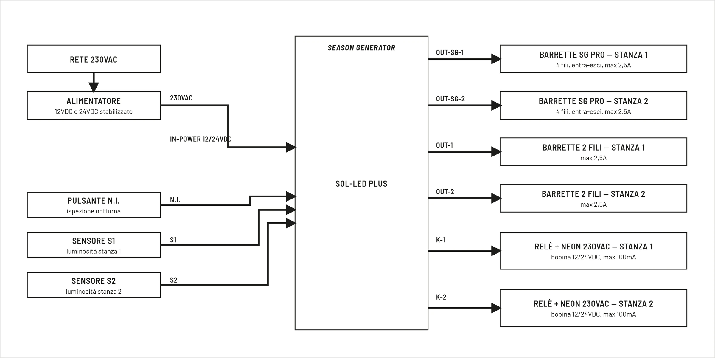
It is not necessary to use all outputs and accessories at the same time. Connect only those required by your system.
Package Contents
Check the presence of the following components:
- SOL-LED+
- User manual
- Any optional accessories
In case of damage due to transport, do not use the device.
Positioning
Install the device in a protected environment.
Avoid:
- direct exposure to the sun;
- excessive humidity;
- condensation;
- conductive powders;
- heat sources.
Ensure adequate ventilation.
Power
SOL-LED+ must be powered exclusively with stabilized direct voltage between:
- 12V DC
- 24V DC
Always check:
- correct polarity;
- correct tension;
- adequate power available.
Power connection
Connect the stabilized power supply to the IN-POWER 12/24VDC terminals, respecting the positive and negative polarity.
See the power diagram before connecting.
LED lighting connection
The LED outputs allow automatic lighting control through progressive brightness adjustment.
Before connecting, check:
- compatible voltage;
- current absorbed;
- correct polarity.
SeasonGenerator PRO Bar Link
The OUT-SG-1 and OUT-SG-2 outputs are dedicated to the SeasonGenerator PRO bars.
| Clamp | Function | Limit |
|---|---|---|
+ | positive LED bar power supply | 2,5 A max |
B | blue LED channel / night light | 100 mA max |
C | PWM sunrise/day/sunset reference | 10 mA max |
- | common negative | 2,5 A max |
Use only compatible modules.
See the Season Generator PRO output diagram.
2-Wire LED Bar Connection
The OUT-1 and OUT-2 outputs are dedicated to 2-wire commercial LED bars powered in DC.
| Clamp | Function | Limit |
|---|---|---|
+ | positive LED bar power supply | 2,5 A max |
- | common negative | 2,5 A max |
Do not connect external LED drivers, LED power supplies, 230V lamps or inductive loads.
For each room, choose the type of output suitable for the installed bar: OUT-SG for SeasonGenerator PRO bars or OUT for 2-wire LED bars.
See the two-wire LED output diagram.
Connection Optional Accessories
Optional accessories connect to the OPT-OUT and K terminals.
Main links:
- remote night inspection button: between
N.I.andGND; - room brightness sensor 1: between
S1andGND; - room brightness sensor 2: between
S2andGND; - room 1 relay coil: on
K-1 + -; - room 2 relay coil: on
K-2 + -.
For the button and sensors see the OPT-OUT diagram. For coils, see the Relay chapter.
Do not apply external voltage to N.I., S1 or S2. Do not connect the mains, lamps or final loads directly to the K-1 and K-2 terminals.
First start-up
After completing all connections:
- Power the device.
- Check that the display turns on.
- Check that the main screen is displayed correctly.
- Check the date and time.
- Proceed with the initial setup.
Check Installation
Before use check:
- correct functioning of the display;
- correct button response;
- correct activation of the outputs;
- correct setting of date and time.
Problems at first startup
If the device does not turn on:
- check the power supply;
- check the polarity;
- check the power supply fuse and the upstream protections;
- check the wiring.
For further information, see the Troubleshooting chapter.