Relay
Introduction
SOL-LED+ was created above all to control the LED bars installed near the cages. These bars allow you to create dawn, daylight, dusk and night light in a gradual and localized way.
In some environments, however, the bars near the cages are not enough to completely illuminate the room. It may therefore be useful to also turn on one or more neon lights, ceiling lights or other lamps intended for the general lighting of the room.
The K-1 and K-2 outputs allow this result to be obtained via an external relay:
K-1follows the main light of room 1;K-2follows the main light of room 2;- each output powers only the low voltage coil of its own relay;
- the power contacts of the relay turn the neon lights or lamps in the room on and off.
In this way SOL-LED+ continues to adjust the LED bars for smooth transitions and, when the light has reached the set level, it can also automatically turn on the general lighting.
On the display, relay management is shown with the screens:
Room relayRelay PWM ON
The relay is managed separately for each room.
Actual menu path
Route:
MENU -> Room relay
In the real menu loop, Room relay comes after Intensity' and before Energy Saving.
Screens displayed:
Room relayRelay PWM ON
Room relay
Enable or disable the active room relay.
Actual display values:
YESNO
Real commands:
UPsetsYES;DOWNsetsNO;ENTERconfirms.
If Room relay is NO, the relay remains off.
If Room relay is YES, the display changes to the Relay PWM ON screen.
Relay PWM ON
Sets the percentage threshold of the main light PWM at which the relay must activate.
Real limits:
- minimum:
0 % - maximum:
100 %
Default value:
80 %
Real commands:
UPincreases the value;DOWNdecreases the value;ENTERsave and return to the main page.
Real behavior of the relay
The relay does not use a dedicated time slot.
The control unit calculates the PWM of the main light in the room and then:
- if
Room relayisNO, forces the relay off; - if there is a
ALLARME_NTCthermal alarm, forces the relay off; - if
Room relayisYESand the PWM percentage is greater than or equal toRelay PWM ON, turns on the relay; - if the PWM percentage is less than
Relay PWM ON, it turns off the relay.
The firmware uses a single configurable threshold: the relay turns on when Relay PWM ON is reached and turns off when the value falls below the same threshold. There is no second switch-off threshold.
The threshold is compared to the PWM of the main light, not to the Night Light.
In Room use -> 1 room mode, the room 2 relay follows the calculated state for room 1.
Practical example with 80% threshold
Suppose we set Relay PWM ON to 80 %.
- At the beginning of dawn the LED bars light up at low intensity and gradually increase.
- As long as the main light remains under the
80 %, the relay remains open and the neon remains off. - When the ramp reaches
80 %, SOL-LED+ energizes the relay coil. - The relay closes the power contacts and turns on the neon or lamps that illuminate the room.5. During sunset the reverse process occurs: when the light drops below the
80 %, the coil is de-powered, the contacts open and the general lighting turns off.
The LED bars can thus continue the final part of the sunset on their own, avoiding the sudden switching off of all the lights in the room.
Relay coil connection
The K-1 and K-2 outputs are not power contacts. They are low voltage DC outputs to power the coil of an external relay, with a maximum current of 100 mA per output.
The available voltage is the same as the device power supply:
- power supply SOL-LED+ to
12 V DC: use a12 V DCrelay coil; - power supply SOL-LED+ to
24 V DC: use a24 V DCrelay coil.
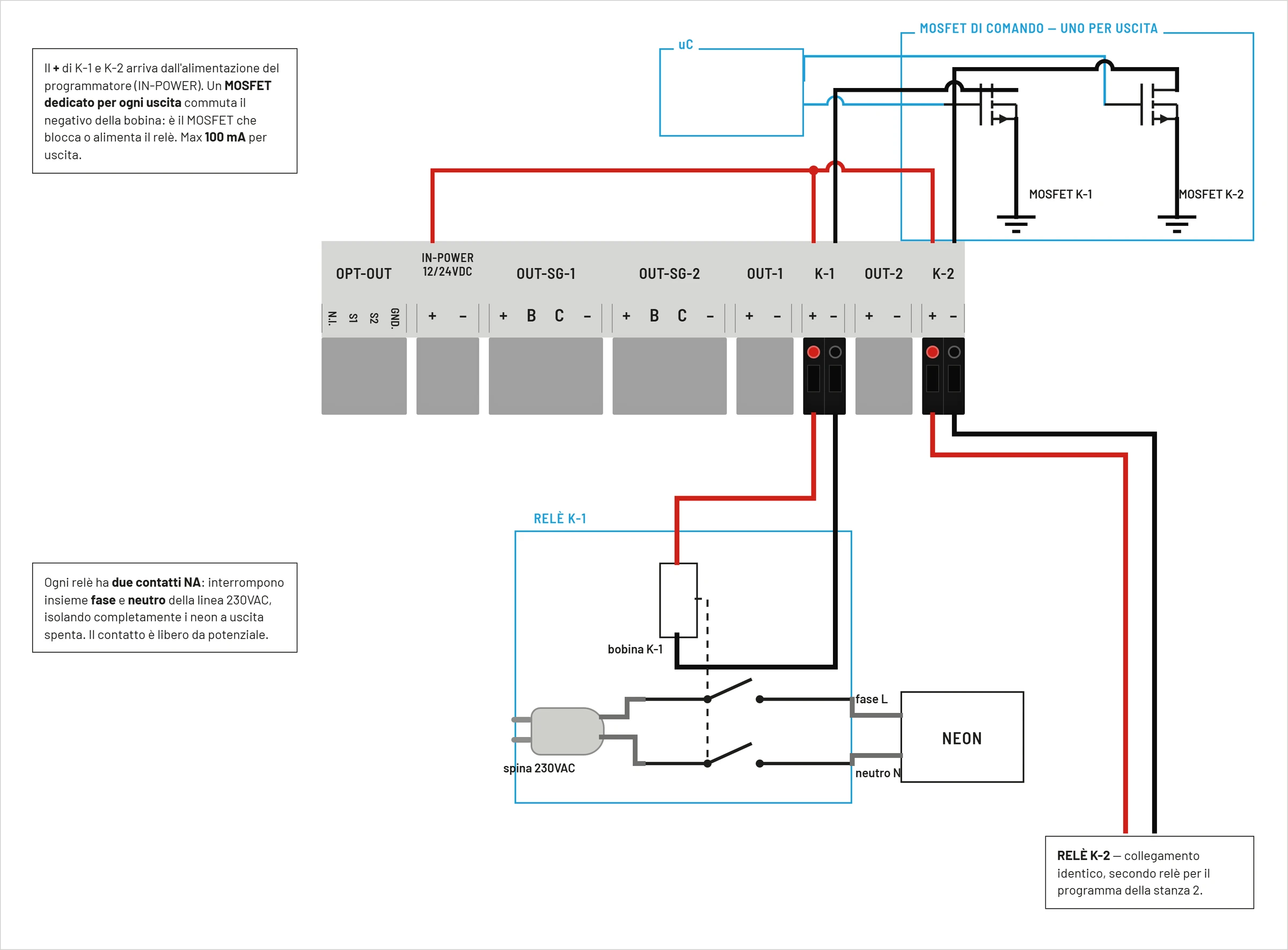
The relay has two electrically separated parts:
- control side: the coil to
12 V DCor24 V DC, connected toK-1orK-2; - power side: the contacts that connect and disconnect the power supply of the neon, ceiling light or lamps.
The diagram shows an example with an external bipolar relay. On the power side, a cable with plug carries the power from the mains socket to the relay contacts; a second cable comes out of the contacts and reaches the neon or the lamps in the room. When the coil is energized, the normally open contacts close and the load turns on.
The chosen relay must have:
- coil with the same supply voltage as SOL-LED+;
- coil absorption not exceeding
100 mA; - contacts sized for voltage, current and type of connected load;
- suitable insulation between low voltage coil and mains contacts.
The final load must be connected to the external relay contacts, not directly to K-1 or K-2. Connections to the electrical network must be carried out by qualified personnel.
Never connect the 230 V AC mains to the K-1 or K-2 terminals. These terminals power exclusively the low voltage coil of the relay. Plug, mains cable, power contacts and neon connection must be made and protected according to the regulations of the electrical system.
Effect during sunrise and sunset
During the dawn ramp, the PWM increases progressively. The relay activates when the ramp reaches the Relay PWM ON threshold.
During the sunset ramp, the PWM progressively decreases. The relay deactivates when the ramp drops below the Relay PWM ON threshold.
Compatibility with programs
The behavior of the relay depends on the PWM generated by the active program.
It is therefore applicable with:
ManualPersonalCustom2AstroGPS Timer- internal tables like
Standard,Song thrush,REDWING,Skylark,Fieldfare,Breeding,Finches,Canaries,Crest Agi