Panel, Indicators and Terminals
This page helps you recognize the front controls, lights and all connections available on SOL-LED+.
The images are specific to the SOL-LED+ model. Connections must only be made with the device turned off and with the power disconnected.
General view
The following image shows the complete front panel, with displays, buttons, indicators of the two rooms and terminals arranged in the same order as the product.
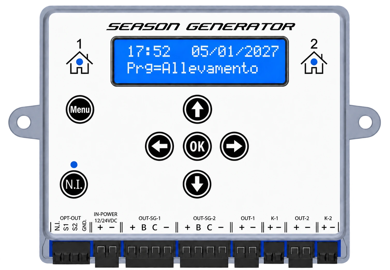
SOL-LED+ can manage two separate programs, indicated as room 1 and room 2. The LEDs next to the room symbols indicate which room is displayed at that moment.
Front controls
| Command | Function |
|---|---|
Menu | enter the menu and move to the next item |
OK | confirms the displayed value and saves the change |
| up/down arrow | increases or decreases values and options |
| left/right arrow | move the editable field or change the displayed room |
N.I. | activates and manages the night inspection |
Front lights
| Spy | Meaning for the user |
|---|---|
home 1 | the screen and controls refer to room 1 |
home 2 | the screen and controls refer to room 2 |
spy N.I. | signals that night inspection is active |
In Room use -> 1 room mode, the outputs of room 2 follow the program of room 1. This mode allows you to distribute the lighting of the same room on two groups of LEDs.
Terminal summary
The table summarizes the terminals from left to right. The acronyms printed on the product remain identical in all languages; instead, the headings and explanations change, to make consultation clear even on the translated manual.
| Terminal | Pins | Function | Current |
|---|---|---|---|
| OPT-OUT | N.I. | remote night-inspection button input, in parallel with the N.I. panel button | — |
| OPT-OUT | S1 | room 1 brightness sensor input | — |
| OPT-OUT | S2 | room 2 brightness sensor input | — |
| OPT-OUT | GND. | common reference for the N.I., S1 and S2 signals | — |
| IN-POWER | + - | controller supply, regulated 12 VDC or 24 VDC | total of all outputs |
| OUT-SG-1 | + B C - | 4-wire SG PRO LED bars, room 1 program | max. 2.5 A |
| OUT-SG-2 | + B C - | 4-wire SG PRO LED bars, room 2 program | max. 2.5 A |
| OUT-1 | + - | commercial 2-wire LED bars or strips, room 1 | max. 2.5 A |
| OUT-2 | + - | commercial 2-wire LED bars or strips, room 2 | max. 2.5 A |
| K-1 | + - | relay-coil control at the PWM threshold, room 1 program | max. 100 mA |
| K-2 | + - | relay-coil control at the PWM threshold, room 2 program | max. 100 mA |
Power supply 12-24 V DC
SOL-LED+ does not connect directly to the mains. The 230 V AC network powers an external stabilized power supply; only the 12-24 V DC output of the power supply needs to reach IN-POWER.
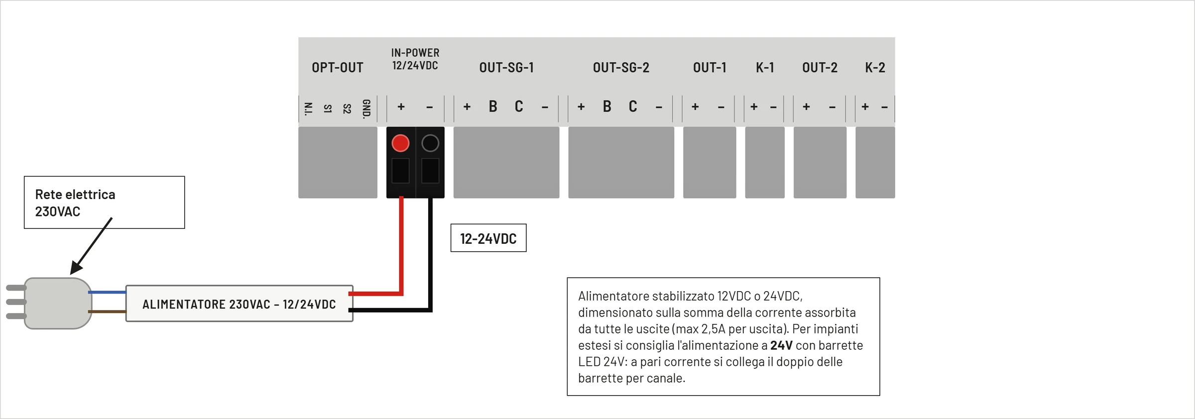
| Clamp | Function |
|---|---|
+ | positive power supply 12-24 V DC |
- | negative power supply |
The power supply must be stabilized and sized on the sum of the current absorbed by all the outputs used. For large systems it is advisable to work on 24 V with 24 V LED bars: with the same current it is possible to power a greater quantity of bars.
4-wire Season Generator PRO outputs
OUT-SG-1 follows the program of stanza 1; OUT-SG-2 follows the room 2 program. These outputs are dedicated to the 4-wire Season Generator PRO rods.
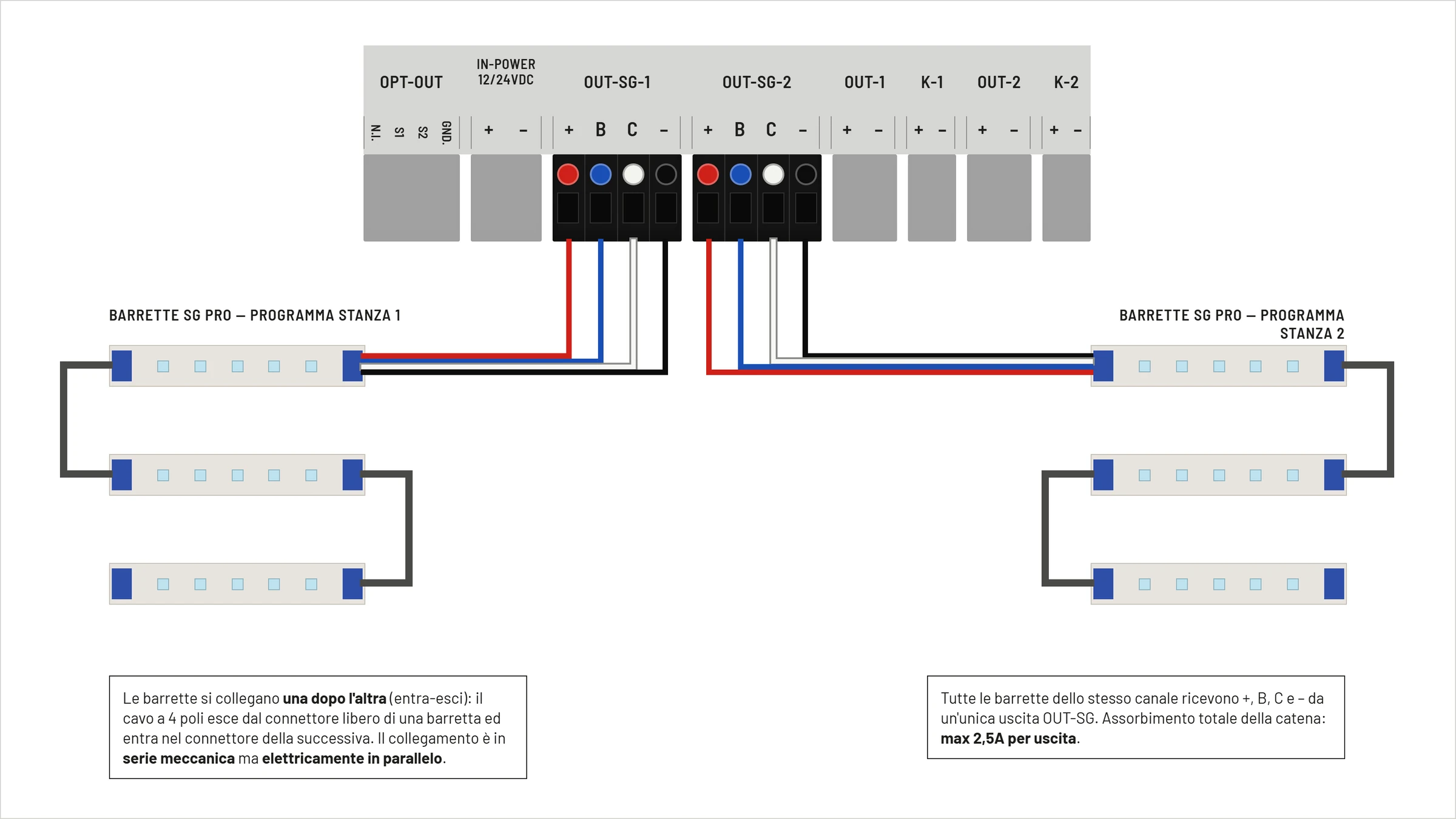
| Clamp | Conductor Color | Function | Limit |
|---|---|---|---|
+ | red | positive LED bar power supply | 2,5 A max |
B | blue | blue LED channel / night light | 100 mA max |
C | white | main PWM reference | 10 mA max |
- | black | common negative / GND | 2,5 A max |
The bars connect one after the other with the in-out system. The arrangement is a chain from a mechanical point of view, but all the bars of the same channel remain electrically in parallel. Total absorption must not exceed 2,5 A per output.
2-Wire Commercial LED Outputs
OUT-1 follows the program of stanza 1; The OUT-2 follows the room 2 program. These outputs power two-wire 12-24 V DC commercial LED bars or strips.
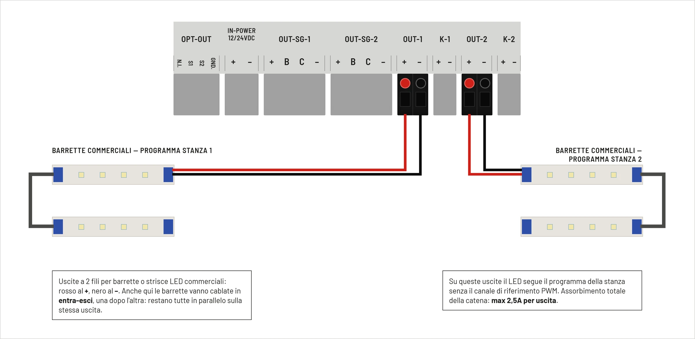
| Clamp | Typical Conductor Color | Function | Limit |
|---|---|---|---|
+ | red | positive LED bar power supply | 2,5 A max |
- | black | common negative | 2,5 A max |
Also in this case the bars can be connected in-out, as long as they remain electrically in parallel. Do not connect external drivers, 230 V lamps, or inductive loads to the LED outputs.
Difference between 2 and 4 wire bars
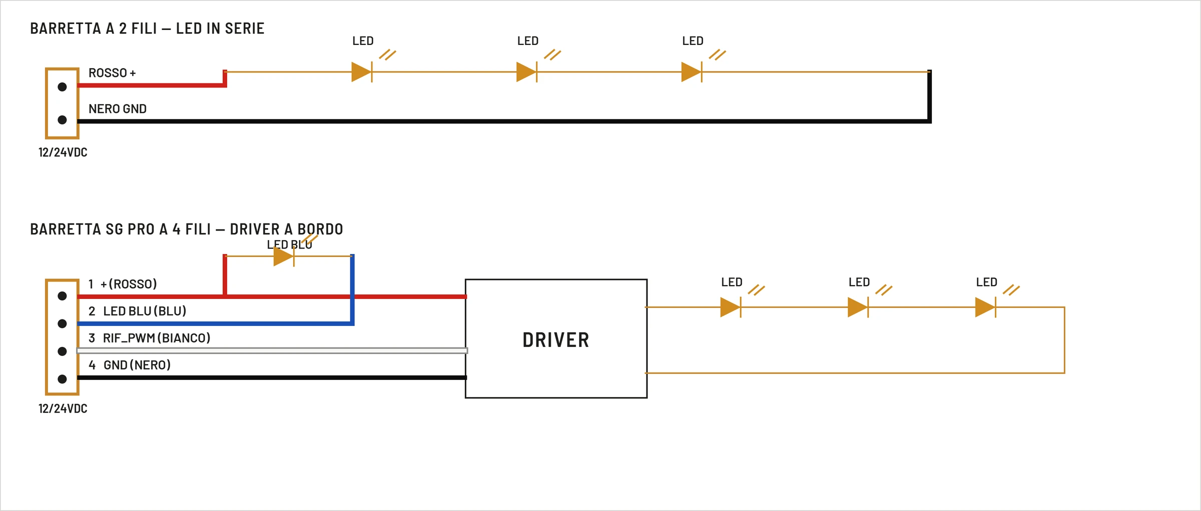
The two-wire rod receives positive and negative directly. The Season Generator PRO bar instead contains a driver and receives power, command for the blue LED, main PWM reference and ground.
Do not interchange the two types of output: the Season Generator PRO bars must be connected to OUT-SG, while the two-wire commercial bars must be connected to OUT.
Optional accessories OPT-OUT
The OPT-OUT clamp brings together the remote night inspection button and the two brightness sensors.
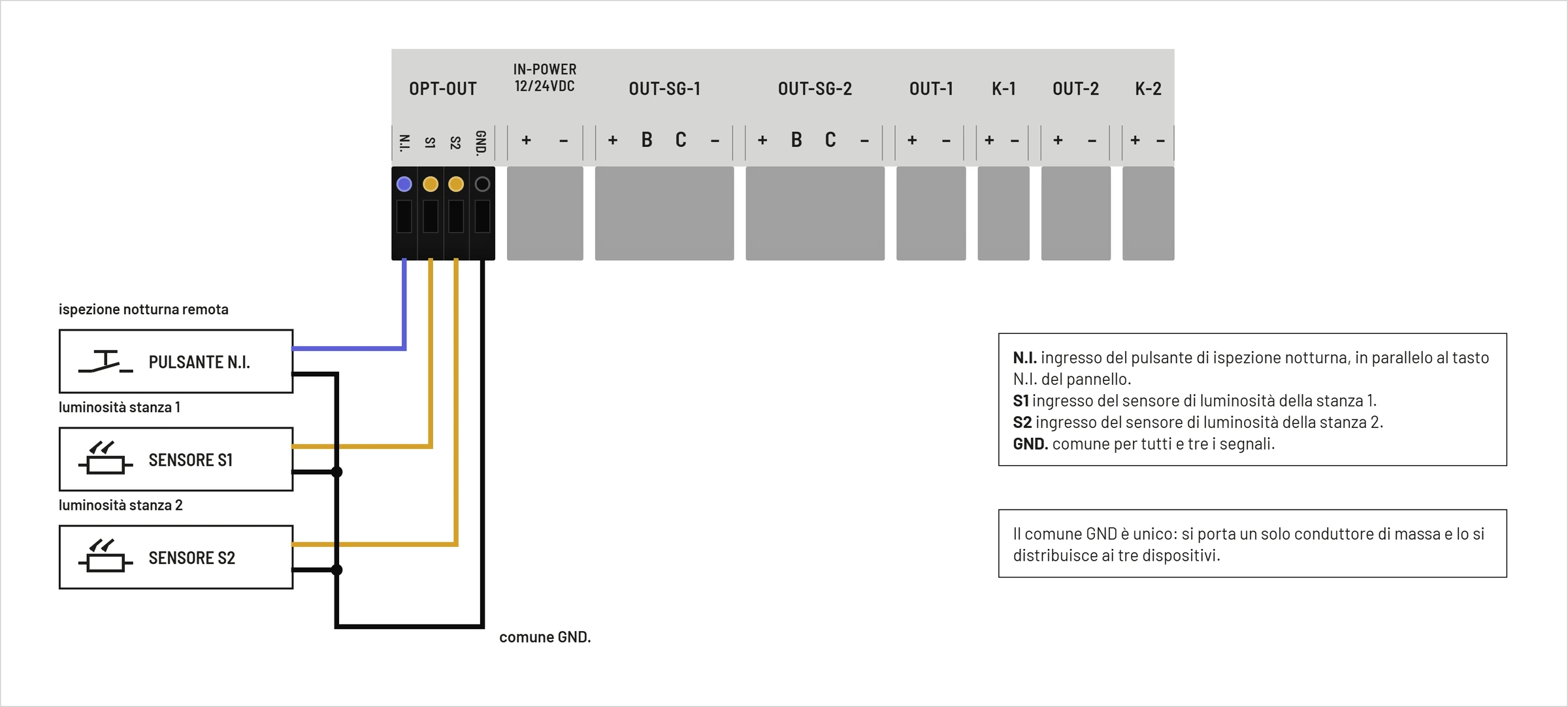
N.I.: remote button in parallel to the button on the panel;S1: room brightness sensor 1;S2: room brightness sensor 2;GND: common of the three signals.
The button must be a simple dry contact. Use only compatible sensors and do not apply external voltages to the N.I., S1, S2 or GND.
Releases K-1 and K-2
The K-1 and K-2 outputs exclusively control low direct voltage relay coils. They are not power contacts and must not directly power neon lights, lamps or the mains.
The voltage follows that of IN-POWER: with power supply to 12 V DC a coil is needed at 12 V DC; with power supply to 24 V DC you need a coil to 24 V DC. Maximum current is 100 mA per output.
The complete connection diagram is shown in the Relay chapter.
Shortcut shortcut
- bars Season Generator PRO:
OUT-SG-1orOUT-SG-2; - two-wire commercial LED bars:
OUT-1orOUT-2; - remote button: between
N.I.andGND; - room sensor 1: between
S1andGND; - room sensor 2: between
S2andGND; - room 1 relay coil:
K-1; - room 2 relay coil:
K-2.
Do not directly connect mains electricity, 230 V lamps, unforeseen LED drivers or final loads to the programmer terminals.